Vehicle Lower Body Structure

a lower body and vehicle technology, applied in the direction of roofs, transportation and packaging, vehicle arrangements, etc., can solve the problems of inefficient transfer of collision load to reinforced members, and achieve the effects of reducing production time and production cost, reducing deformation of vehicle compartments, and increasing strength

Inactive Publication Date: 2009-10-01
TOYOTA JIDOSHA KK
View PDF5 Cites 16 Cited by
  • Summary
  • Abstract
  • Description
  • Claims
  • Application Information

AI Technical Summary

Benefits of technology

[0015]In this case, the reinforcement member may be formed integrally with the floor cross-member. Thus, it is not necessary to connect the reinforcement member and the floor cross-member to each other. As a result, production time and production cost are reduced.
[0016]The reinforcement member may be connected, at an end portion, to a vehicle center frame member that is arranged at the lateral center of the vehicle and that extends in the longitudinal direction of the vehicle. In this case, because the end portion of the reinforcement member is connected to the vehicle center frame member, the collision load, applied to the windshield pillar from a position above the rocker, is directly transferred to the vehicle center frame member via the reinforcement member to be dispersed. It is also possible to increase the strength with which the windshield pillar is supported. As a result, it is possible to further reduce deformation of the vehicle compartment due, for example, to an offset collision.
[0017]The vehicle center frame member may be a floor pan tunnel member. Thus, it is possible to transfer the collision load, applied to the windshield pillar from a position above the rocker, directly to the floor pan tunnel portion via the reinforcement member thereby dispersing the collision load.
[0018]The vehicle center frame member may be a floorpan reinforcement member that is arranged between a floor tunnel member and the rocker, and that extends in the longitudinal direction of the vehicle. Thus, it is possible to transfer the collision load, applied to the windshield pillar from a position above the rocker, directly to the floor tunnel portion via the reinforcement member, and thereby dispersing the collision load. Connecting the reinforcement member to the floorpan reinforcement member, which is close to the windshield pillar, makes it possible to reduce the length of the reinforcement member, thereby enhancing the efficiency of dispersing the collision load.
[0019]The vehicle lower body structure according to the first aspect of the invention may further include a bulkhead that is provided inside the windshield pillar, and that is arranged so as to face the reinforcement member with the windshield pillar interposed between the reinforcement member and the bulkhead. In the vehicle lower body structure, providing the bulkhead so as to face the reinforcement member increases the strength with which the windshield pillar is supported, and enhances the efficiency of transferring the collision load from the windshield pillar to the reinforcement member.
[0020]According to the first aspect of the invention, by providing the reinforcement member that is connected to the windshield at a position above the rocker in the vehicle-height direction and that transfers the collision load in the vehicle-width direction toward the lateral center of the vehicle makes it possible to more efficiently disperse the load due, for example to an offset collision.

Problems solved by technology

However, if a collision load is applied to the windshield pillar from a position above the rocker, the collision load is not efficiently transferred to reinforced members such as the floor pan tunnel member to be dispersed.

Method used


Image

  • Vehicle Lower Body Structure
  • Vehicle Lower Body Structure
  • Vehicle Lower Body Structure

Examples


Embodiment Construction

[0045]Hereafter, example embodiments of the invention will be described in detail with reference to accompanying drawings. In the drawings, the same or corresponding portions will be denoted by the same reference numerals. In the specification, the positional expressions such as “front”, “rear”, “right”, “left”, “above”, and “below” denote these positions when the host vehicle is moving forward.

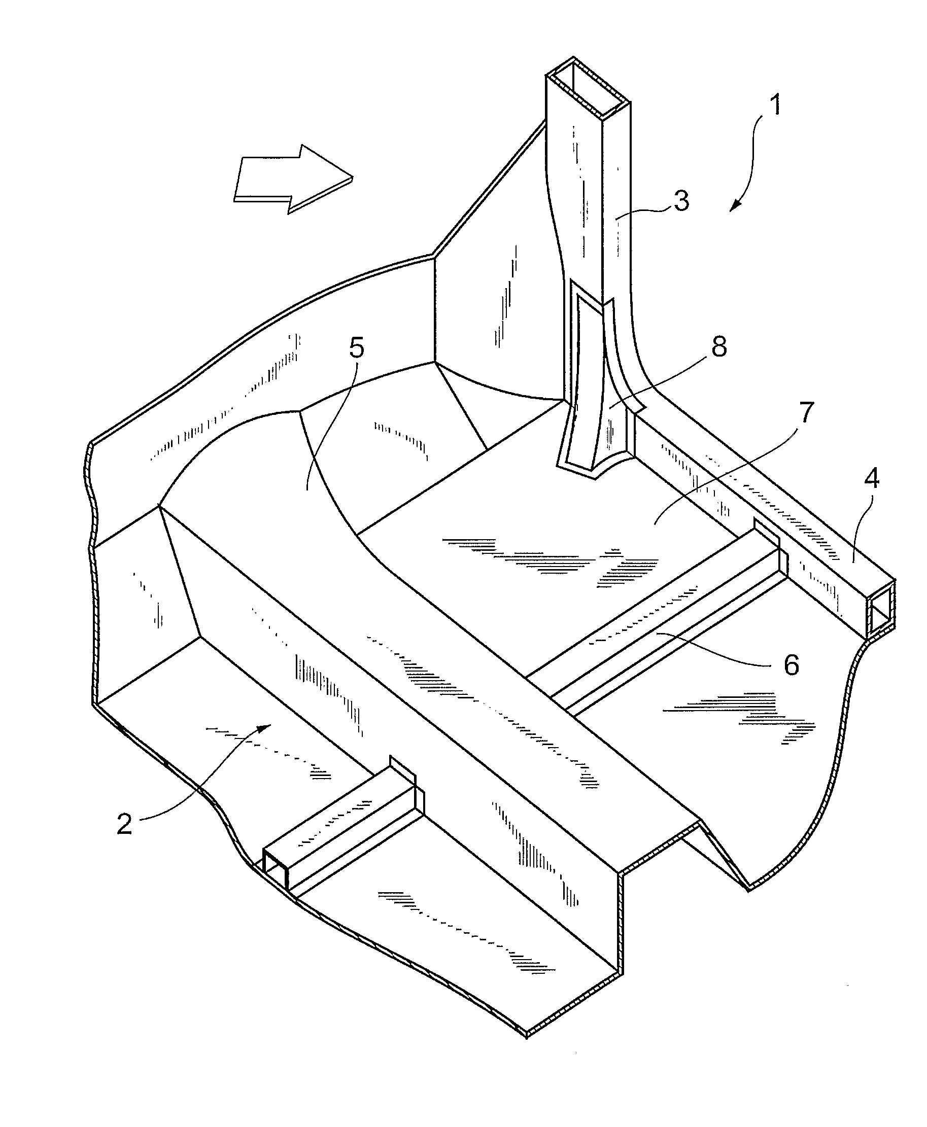
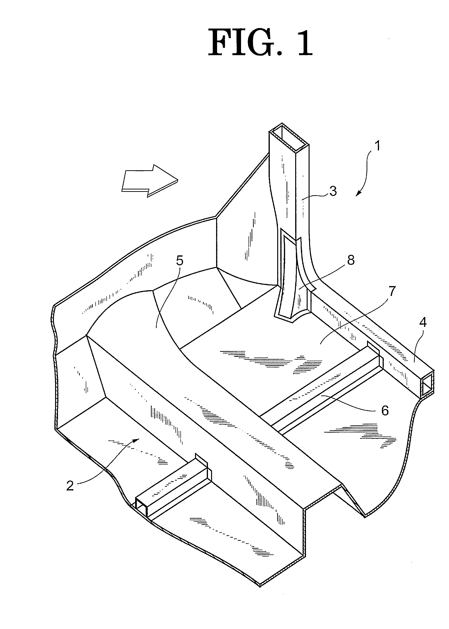
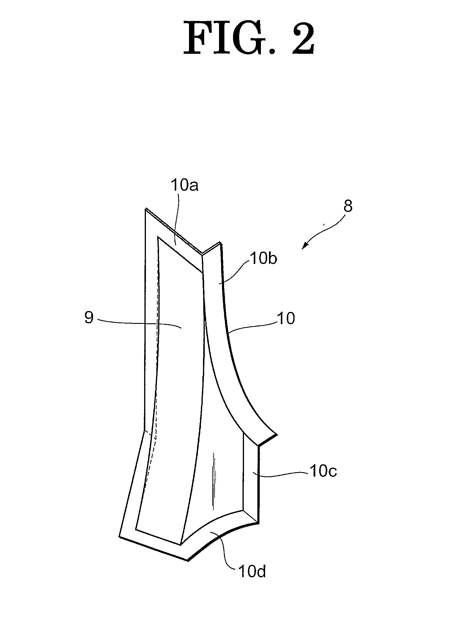
[0046]First, a vehicle lower body structure 1 according to a first embodiment of the invention will be described in detail with reference to FIGS. 1 and 2. FIG. 1 is the perspective view showing the vehicle lower body structure 1 according to the first embodiment of the invention. FIG. 2 is the perspective view of a pillar brace 8 in the vehicle lower body structure 1.

[0047]As shown in FIG. 1, the vehicle lower body structure 1 includes a vehicle compartment 2; a windshield pillar 3 that is arranged at the side portion of a vehicle and that extends in the vehicle-height direction; and a rocke...


PUM


Abstract

A vehicle lower body structure (1) including a vehicle compartment; a windshield pillar (3) that is provided at the side portion the vehicle and that extends in the vehicle-height direction; a rocker (4) that is connected, at the front end portion, to the lower end portion of the windshield pillar (3) and the extends in the longitudinal direction of the vehicle; a floor tunnel member (5) that is provided at the lateral center portion of the vehicle and that extends in the longitudinal direction of the vehicle; a floor cross-member (6) that is connected to the rocker (4) and the floor tunnel member (5) and that extends in the vehicle-width direction; and a floor panel (7) that is connected to the windshield pillar (3), the rocker (4), the floor tunnel member (5), and the floor cross-member (6) and that forms the floor of the vehicle compartment.

Description

BACKGROUND OF THE INVENTION[0001]1. Field of the Invention[0002]The invention relates to a vehicle lower body structure.[0003]2. Description of Related Art[0004]Japanese Patent Application Publication No. 2003-237636 (JP-A-2003-237636) describes a vehicle structure with which a load applied to a vehicle due to a collision (hereinafter, referred to as a “collision load”) is transferred to a frame structural member of the vehicle, whereby deformation of a vehicle compartment is minimized. In the vehicle structure described in JP-A-2003-237636, a floor cross-member is attached to the floor pan and extends obliquely from a side sill (hereinafter, referred to as a “rocker”) toward a lateral center member (hereinafter, referred to as a “floor pan tunnel member”).[0005]In the described structure, a collision load transferred to the rocker when an offset collision occurs is efficiently transferred via the floor cross-member to the floor pan tunnel member.[0006]However, a bumper beam is usua...

Claims


Application Information

Patent Timeline
Patent Type & Authority Applications(United States)
IPC IPC(8): B62D25/20
CPCB62D25/04B62D25/2036B62D25/2018B62D21/02B62D21/15
Inventor TAMAKOSHI, KOJI
Owner TOYOTA JIDOSHA KK
Why Eureka
Try Eureka