Shock absorbing wheel

a technology rim, which is applied in the field of shock absorption wheel, can solve the problems of insufficient use of sinus shaped arms in order to provide shock absorption properties, the possibility of providing a great length of stroke, and the hub comprises a relatively complex configuration, so as to increase the rigidity of the rim, reduce wear, and fast and cost-effective production

Inactive Publication Date: 2009-10-01
AGRIA TRADGARDSMASKINER I KALLERED
View PDF15 Cites 8 Cited by
  • Summary
  • Abstract
  • Description
  • Claims
  • Application Information

AI Technical Summary

Benefits of technology

[0007]The arms can also be protected by means of round support plates arranged on both sides of the wheel and arranged at the hub and these plates can support the inside of the rim before the permitted spring force is exceeded on the arm. It is also possible to attach additional plates on the above mentioned plates and then with a larger dimension and these can function as cover plates to prevent dirt and similar from intrusion.
[0008]In an embodiment on the present invention is the sinusoidal shaped form in the second and third sections substantially aligned with a radius curvature which runs parallel with the rim so that the sinusoidal shaped form is provided along the radius curvature. The embodiment fully utilizes the function of the sinusoidal arms and the arms different junction positions for shock absorbing properties. Further, the embodiment secures that the arms are only exposed to a minimum of contact surfaces if the shock absorbing wheel is imparted with a force exceeding the spring force of the arms. The sinusoidal shaped arms in the second and the third sections may form a full sinusoidal wave between the first and the forth section of the arms. Preferably, the first and the forth sections may be equally long. The second and the third sections may be substantially equally long as measured along the radius curvature. It is believed that the symmetric arrangement of the arms of the wheel provides not only a balanced wheel but homogenous force absorption. In one embodiment of the present invention, the hub, arms and rim are manufactured in one piece of material. This enables fast and cost effective production of shock absorbing wheels. However, it is within the boundaries of the present invention that the arms are separate parts with respect to each other. This may be beneficial from maintenance and repair point of view.
[0009]The shock absorbing wheel may further comprise at least one support disc arranged to the hub and / or the rim so as to provide tor a deformation stop to the arms, preferably at least two support discs, more preferably circular support discs. In cases of two supports disc, the support discs may be attached to the hub and the rim respectively. The support disc solves a number of different problems, some problems which are solved are; Protection against external negative forces subjected to the shock absorbing wheel. Supporting the rigidity of the shock absorbing wheel in a direction transverse of the rotational direction. More specifically in can be mentioned that the support disc attached to the rim provides for an increased rigidity of the rim, especially in those areas along the rim which are between the arms of the shock absorbing wheel. A support disc attached to the rim can further decrease the wear, e.g. from a support disc attached to the hub, or possibly from the cam of the bends as described above. A support disc attached to the rim is specifically beneficial for increasing the rigidity of the relevant part of the shock absorbing wheel. Additional benefits are that the manufacturing tolerance of the shock absorbing wheel can be lowered due to the support discs. As a consequence, a high manufacturing rate can be prioritized.

Problems solved by technology

This type of shock absorber has some limitations however concerning the possibility of providing a great length of stroke and resistance to forces larger than the permitted spring force at the same time the spring wheel is rigid with respect to revolving.
The arms can be said to be substantially sinus shaped, however, the wheel described in the publication fails to fully utilize the sinus shaped arms in order to provide shock absorbing properties.
However, the hub comprises a relatively complex configuration, without adequate shock absorbing properties.

Method used


Image

  • Shock absorbing wheel
  • Shock absorbing wheel
  • Shock absorbing wheel

Examples


Embodiment Construction

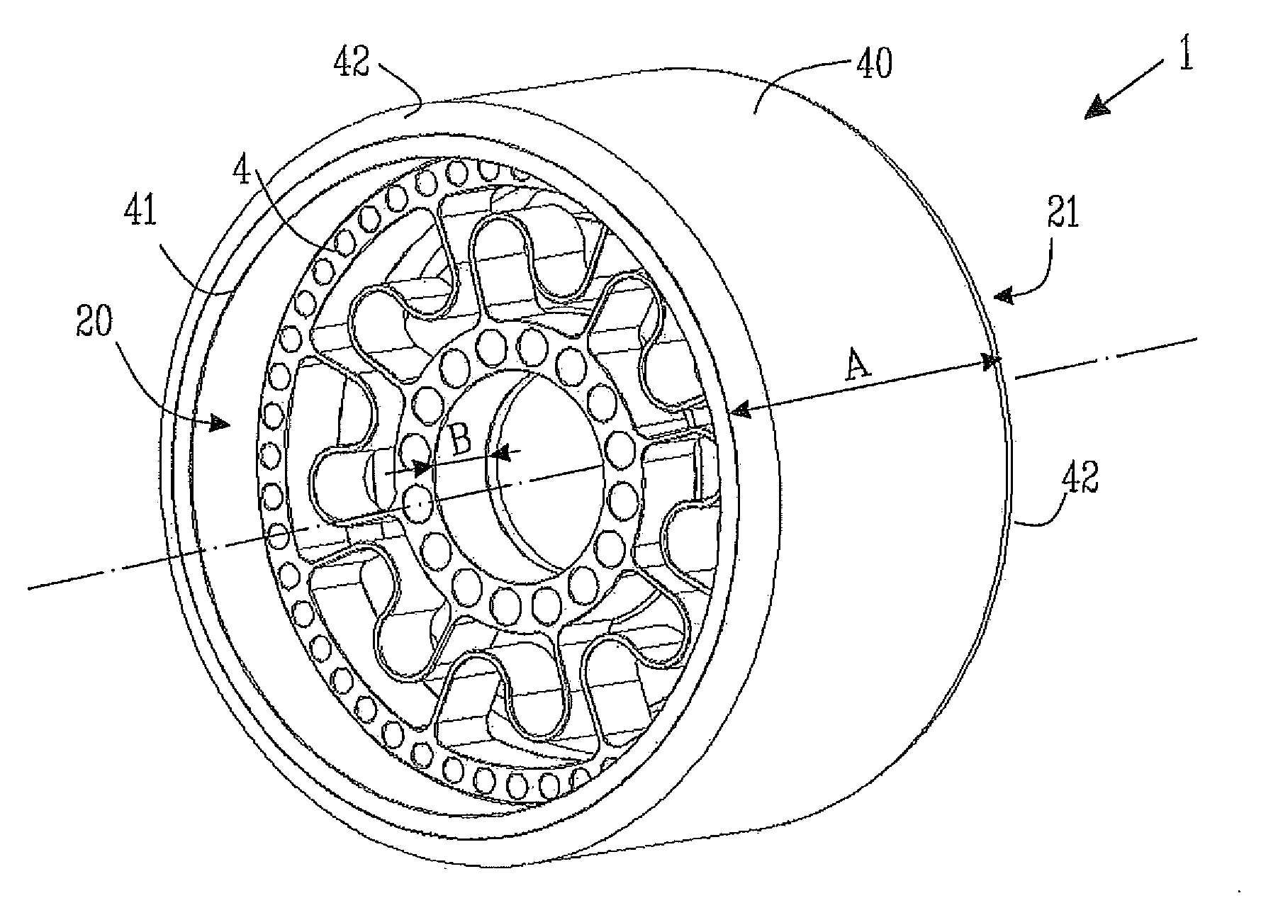
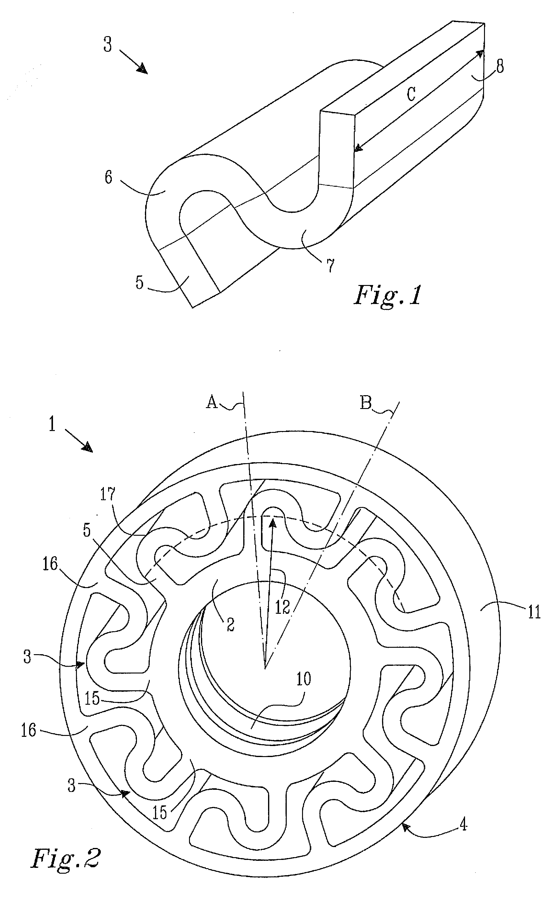
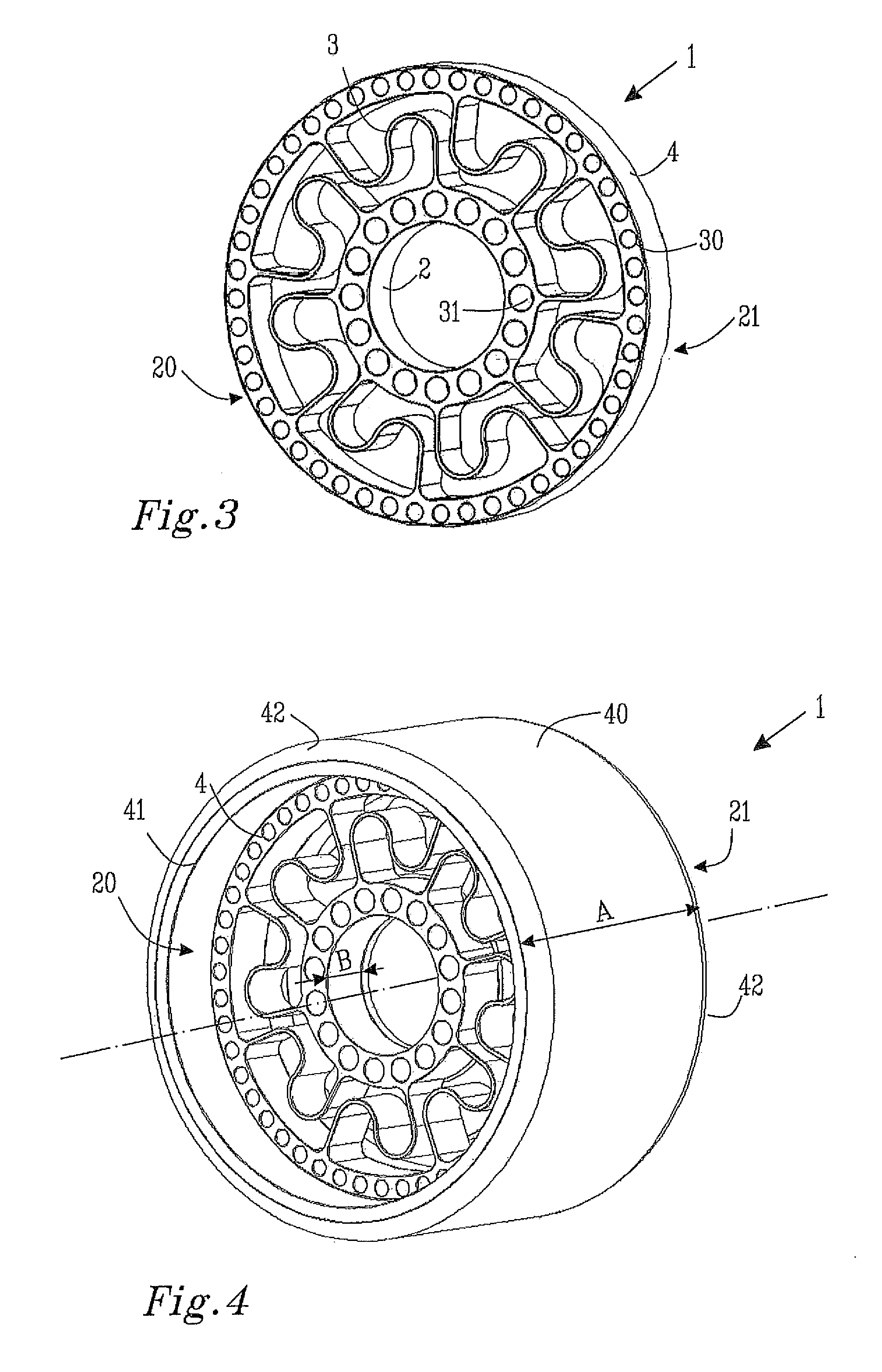
[0020]The invention will now be described for exemplifying purpose in greater detail with the aid of embodiments and with reference to the attached drawings. According to one embodiment of the present Invention, FIG. 1 shows an arm with a sinusoidal shaped extension according to the present invention, the arms extended 5 part which is in a first section and one end attached to a hub and further into a second section which comprises a bend 6 which bends away from the rim 4 so that a space between the rim 4 and the cam of the bend. Further in the third section, a bend 7 that bends away from the hub 2 that also leaves a space between the cam of the bend 7 and the hub 2. The second sections bend 6 is connected to the bend 7 of the third section and arranged so that a sinusoidal shaped wave is provided. Further in the fourth section, an extended 8 part which makes the arm 3 second end and attached into the rim 4. To manufacture the wheel, for example, different types of plastics may be u...


PUM


Abstract

The present invention relates to a shock absorbing wheel with shock absorbing properties, the wheel comprises a hub, arms and a rim. The hub comprises radial junctions between the arms and the hub, additionally the rim comprises radial junctions between the arms and the rim, wherein between the radial junctions of the hub and the rim the arms are arranged with a substantially sinusoidal shaped form. The arms further comprise a first, a second, a third and a fourth section, wherein in the first section, the arms extend from the radial junctions between the arms and the hub in a first radial direction A, and in the forth section, the arms extend from the radial junctions between the arms and the rim in a second radial direction B. The sinusoidal shaped form is arranged in the second and the third sections of the arms. The present invention is said to provide for a cost effective wheel with good shock absorbing properties.

Description

TECHNICAL FIELD[0001]The present invention relates to a shock absorbing wheel with shock absorbing properties, the shock absorbing wheel comprises arms with a substantially sinusoidal form.BACKGROUND OF THE INVENTION[0002]Shock absorbing wheels with different shapes of the arms of the wheel are known for use with e.g. machines. Wheels are used today in a number of different ways, and in some cases it might be advantageous with shock absorbing wheels, e.g. vehicles, machines and in other devices where shock absorbing wheels are required. There are several shock absorbing wheels on the market. This type of shock absorber has some limitations however concerning the possibility of providing a great length of stroke and resistance to forces larger than the permitted spring force at the same time the spring wheel is rigid with respect to revolving.[0003]A shock absorbing wheel is described in the U.S. publication Pat. No. 1,489,233. The wheel comprises a hub, arms and a rim. The arms can ...

Claims


Application Information

Patent Timeline
Patent Type & Authority Applications(United States)
IPC IPC(8): B60B1/06B60B25/00
CPCB60B9/26B60B5/02
Inventor KARLSSON, STIG-ERIK SE-YOUNG
Owner AGRIA TRADGARDSMASKINER I KALLERED
Why Eureka
Try Eureka