

Movable Table Unit
- Summary
- Abstract
- Description
- Claims
- Application Information
AI Technical Summary
Benefits of technology
Problems solved by technology
Method used
Image

Examples
first embodiment
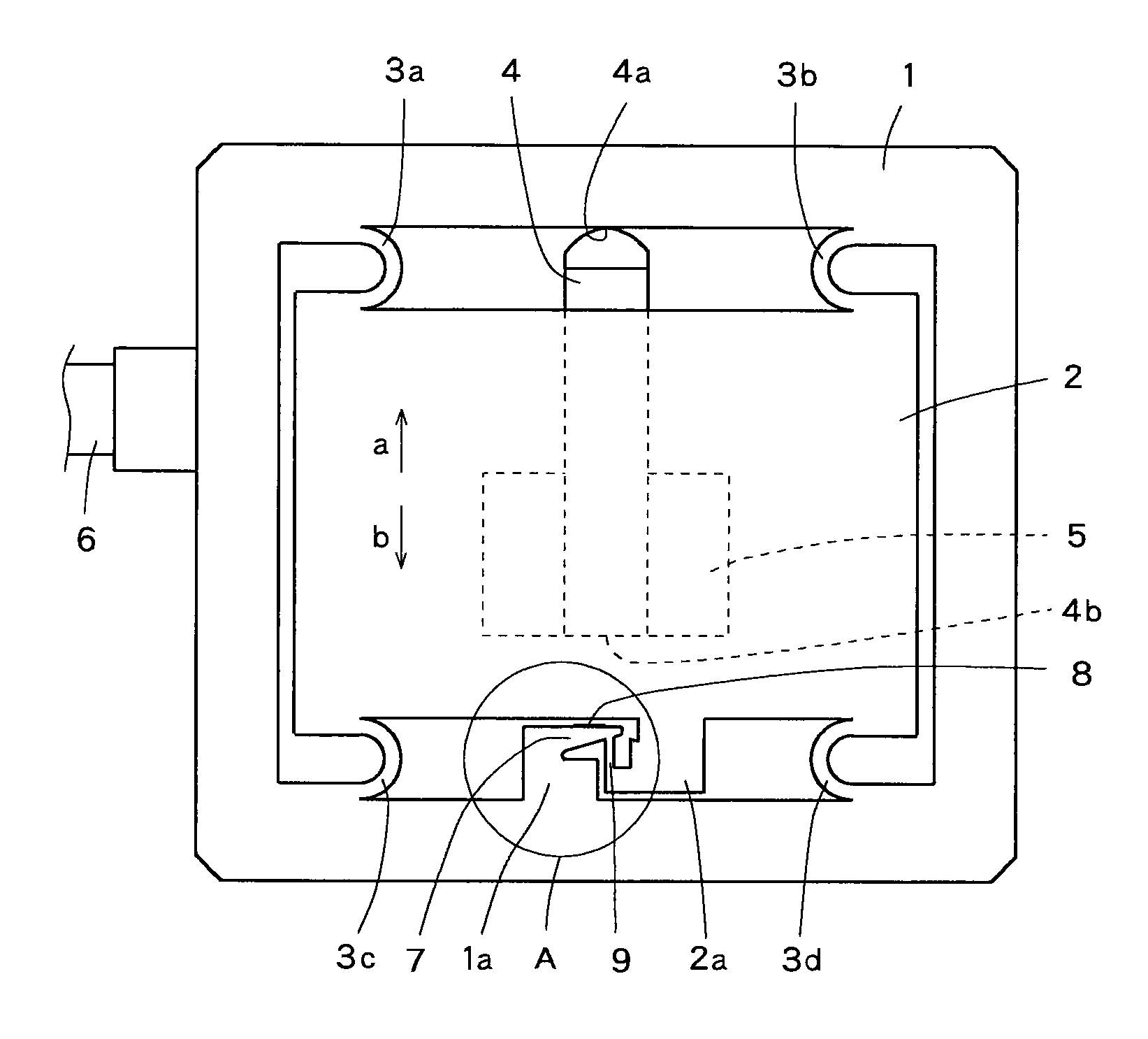
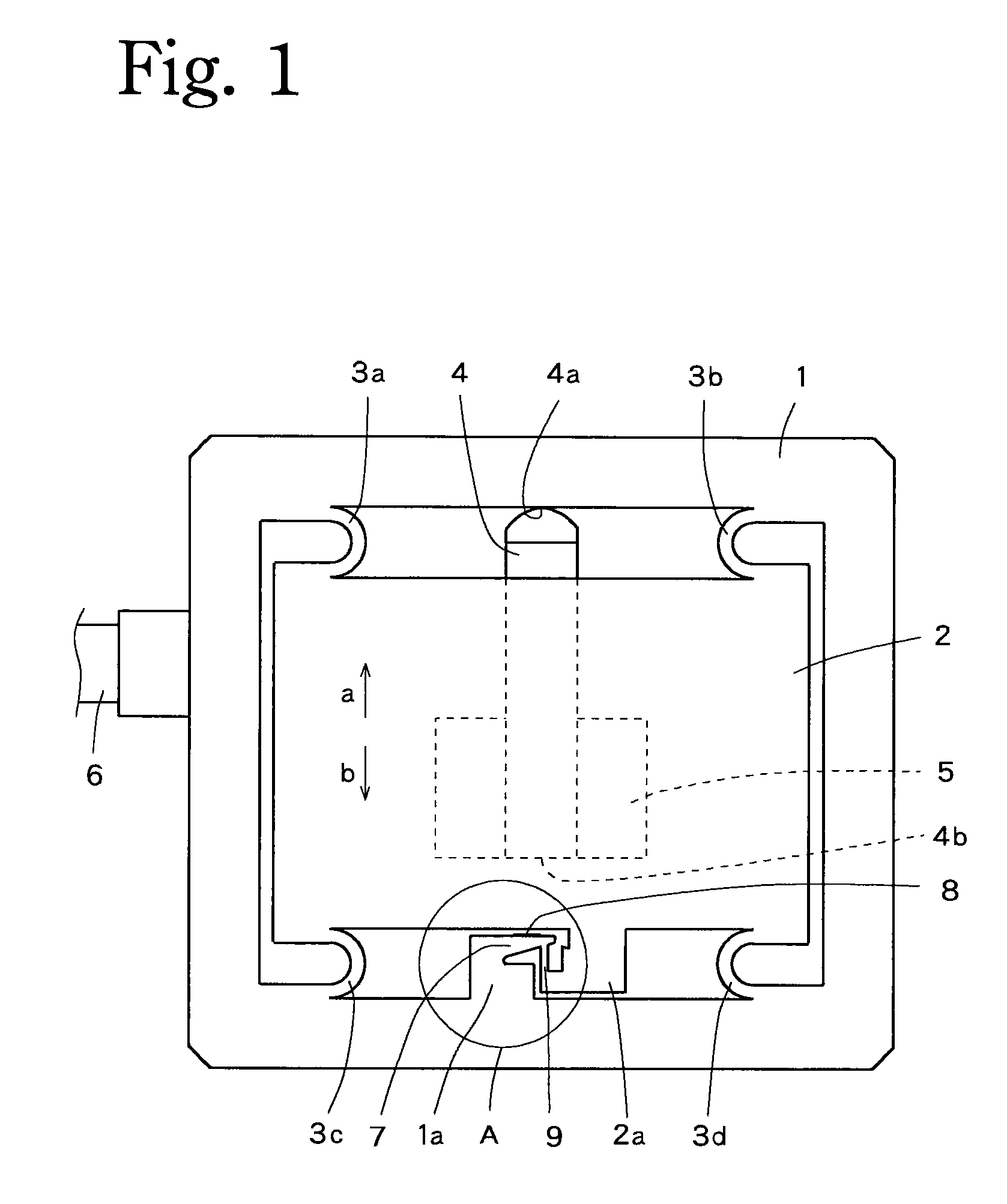
[0033]A first embodiment illustrated in FIGS. 1 to 3 comprises a metallic movable table 2 provided in a quadrangular-frame-shaped metallic stationary base 1, and spring members 3a, 3b, 3c, 3d respectively comprising U-shaped plate springs and disposed in the four corners of the movable table 2. The movable table 2 is coupled to the stationary base 1 through the spring members 3a to 3d.
[0034]In the first embodiment, the stationary base 1, the movable table 2 and the spring members 3a to 3d are formed in one piece, but in this case the stationary base 1 and the movable table 2 posses overwhelmingly higher stiffness than that of the spring members 3a to 3d, and can be almost regarded as a rigid body.
[0035]A piezoelectric element 4 is disposed on a width-direction central portion of the rear side face of the movable table 2. The piezoelectric element 4 has a leading end 4a making contact with the inner side of the stationary base 1 and the opposing tail end 4b fixedly attached to the r...
second embodiment
[0058]The beam used as the strain occurrence site of the present invention is not limited to being a beam of uniform strength. Instead of this, a beam of uniform thickness which is uniform in thickness throughout its length may be used as in a second embodiment illustrated in FIG. 5.
[0059]The movable table unit of the second embodiment as illustrated in FIG. 5 comprises a beam of uniform thickness 10 which is used as the strain occurrence site of the present invention, instead of the beam 7 of the first embodiment, with the strain gauge 8 affixed to the beam 10. The other components in the second embodiment apart from the beam 10 are the same as those in the first embodiment. Therefore, the same component elements as those in the first embodiment are designated by the same reference numerals as those in the first embodiment. FIG. 1 as well as FIG. 5 is referred to in the following description.
[0060]Similar experiments to those in the first embodiment were made on the movable table u...
third embodiment
[0069]In the third embodiment, a metal-made block is divided into a stationary base 1 and a movable table 2 which are defined by incisions 12. The incisions 12 are used to form the parallel springs 11a to 11d, the beam 7 and the like.
[0070]The movable table2 of the third embodiment has a flat face 2b formed inside the outer periphery defined by the incisions 12 and extending toward the surface of the unit more than the other portions.
[0071]Reference numeral 13 in FIG. 8 denotes a fixing screw hole for mounting a work-piece on the movable table 2, and reference numeral 14 denotes a through-hole receiving a bolt for mounting the stationary base 1 on a pedestal or the like.
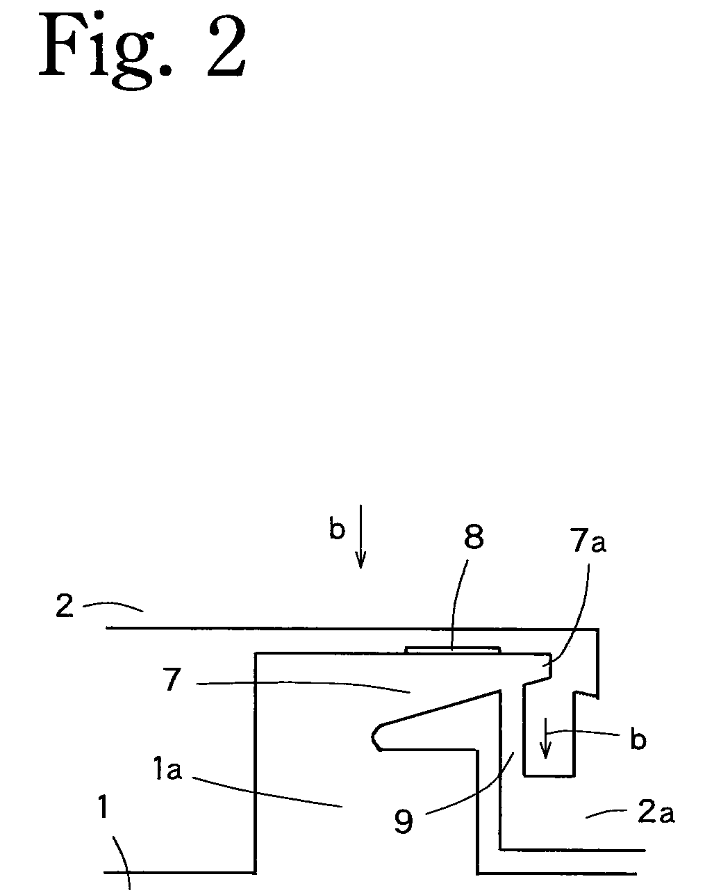
[0072]In the movable table unit of the third embodiment, the relationship between the amount of strain detected by the strain gauge 8 and the amount of displacement of the movable table 2 is realized as in the case of the first embodiment illustrated in FIGS. 3 and 4, because the beam of uniform strength 7 is affixed...
PUM
 Abstract
Description
Claims
Application Information