

Protection circuit
a protection circuit and circuit technology, applied in the direction of semiconductor devices, electrical apparatus, transistors, etc., can solve the problems of insufficient protection performance compared to thyristor, difficult rapid triggering of thyristor-type electrostatic protection circuits, and more easily destroyed semiconductor devices by static electricity, so as to achieve hardly cause a latch-up and easy triggering
- Summary
- Abstract
- Description
- Claims
- Application Information
AI Technical Summary
Benefits of technology
Problems solved by technology
Method used
Image

Examples
first exemplary embodiment
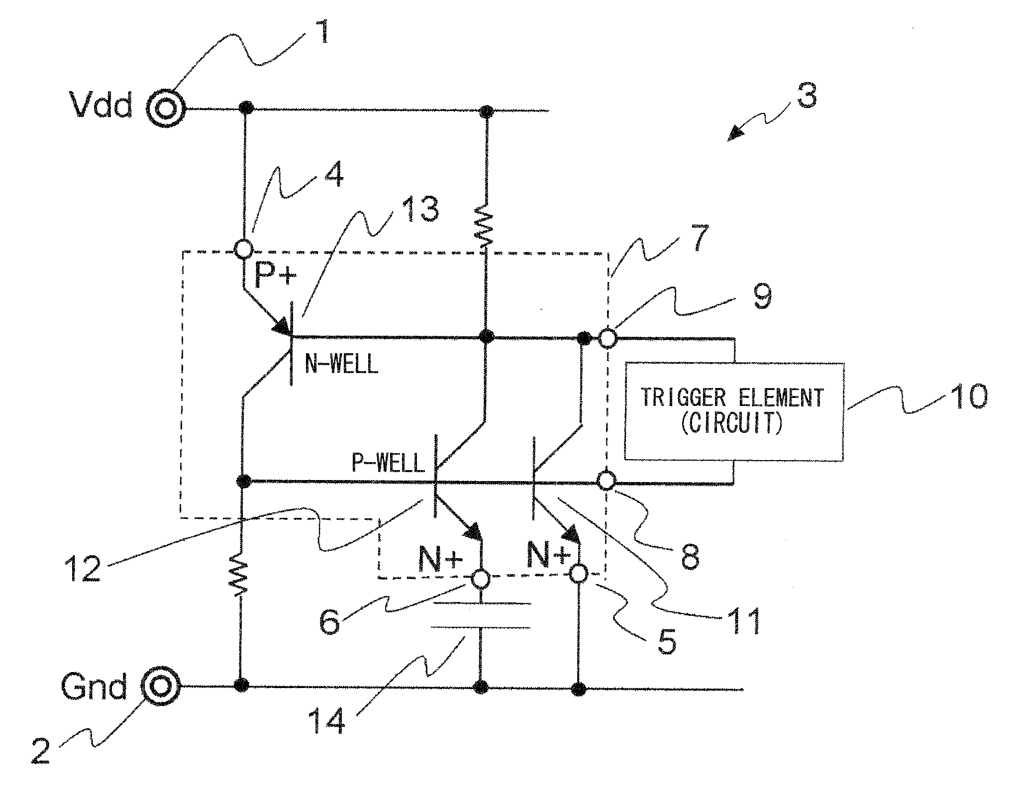
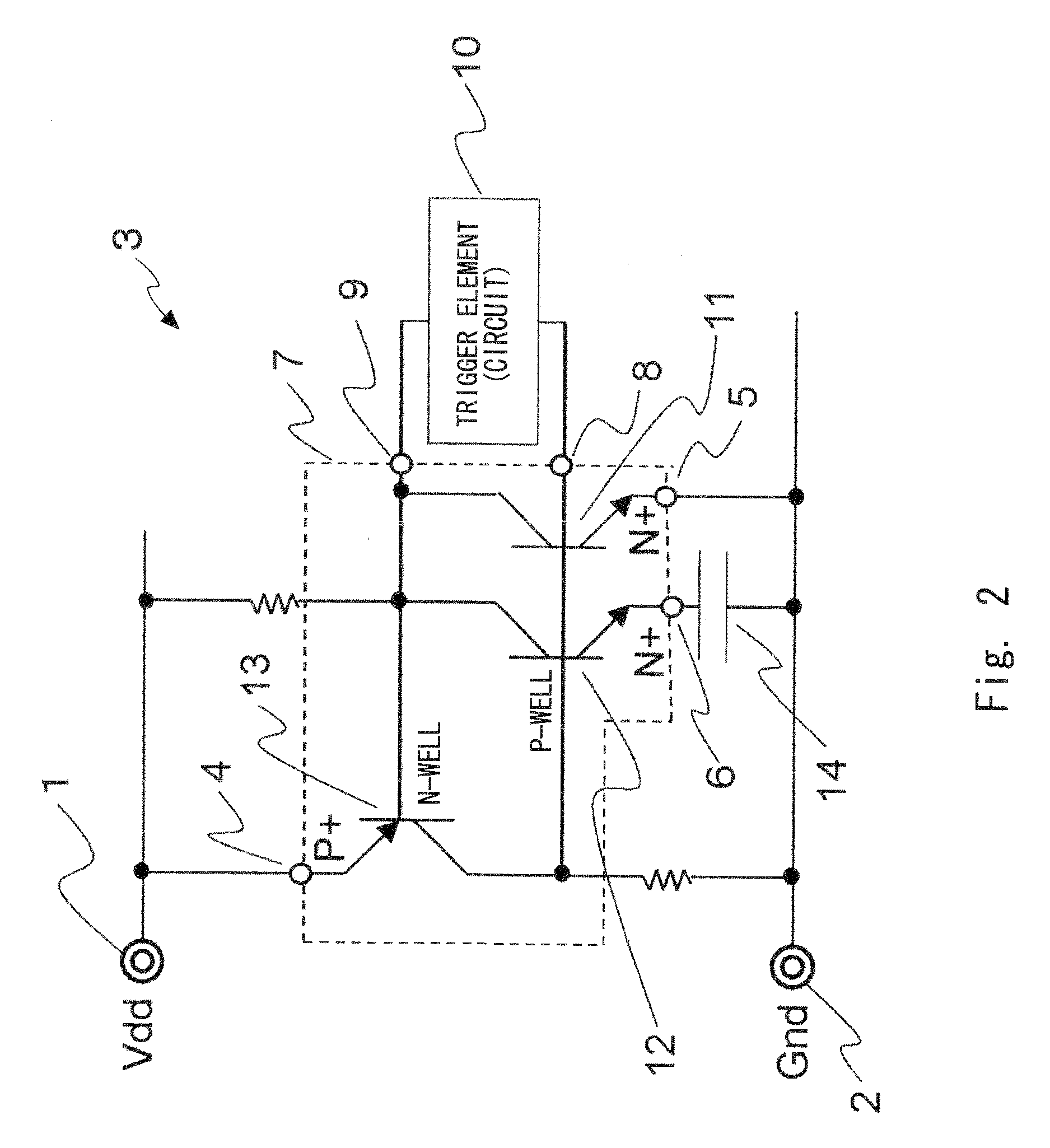
[0054]A first exemplary embodiment of the present invention shows an example in which a protection circuit is used to protect power supply terminals. FIG. 2 is a circuit diagram showing the protection circuit according to the first exemplary embodiment. FIG. 3 is a cross-sectional view showing a multi-cathode thyristor for use in the protection circuit shown in FIG. 2. FIG. 4 shows an example of an internal circuit of a trigger element 10 which is added to the cross-sectional view of FIG. 3, for facilitating the understanding of circuit operation. FIG. 5 is a plan view of the multi-cathode thyristor according to the first exemplary embodiment.
[0055]First, the configuration of the circuit according to the first exemplary embodiment will be described with reference to FIG. 2. A thyristor-type protection circuit 3 is provided between a first power supply VDD terminal 1 and a second power supply GND terminal 2. The protection circuit 3 includes a capacitor element 14, a multi-cathode th...
second exemplary embodiment
[0061]Next, a second exemplary embodiment of the present invention will be described with reference to the drawings. FIG. 6 is a plan view of a multi-cathode thyristor according to the second exemplary embodiment that is disposed on a semiconductor substrate. While the cathode region is divided into two regions in the first exemplary embodiment, the cathode region is divided into four regions in the second exemplary embodiment. Further, according to the second exemplary embodiment, three cathode regions 5B 6A and 6B are sandwiched between the anode 4 and the cathode region 5A that is farthest from the anode 4 among the four cathodes regions. The optimum positional relationship among the anode 4 and the first and second cathodes may vary depending on the process change or the like. When the cathode regions are formed in the manner as in the second exemplary embodiment, the relative position and size of each of the first and second cathodes with respect to the anode 4 can be changed b...
third exemplary embodiment
[0062]Next, a third exemplary embodiment of the present invention will be described with reference to the drawings. The third exemplary embodiment shows an example of a protection circuit for use in protecting the power supply terminals, as in the first exemplary embodiment. FIG. 7 is a circuit diagram showing a circuit according to the third exemplary embodiment. FIG. 8 is a cross-sectional view showing the configuration of the circuit. FIG. 9 shows an example of an internal circuit of the trigger element 10 which is added to the cross-sectional view of FIG. 8, for facilitating the understanding of the circuit operation. In the third exemplary embodiment, components and operations identical to those of the first exemplary embodiment are denoted by the same reference numerals, and a description thereof is omitted.
[0063]First, the third exemplary embodiment shown in FIG. 7 is compared with the first exemplary embodiment shown in FIG. 2. While the capacitor element formed on the semic...
PUM
 Abstract
Description
Claims
Application Information