Fuel cell system and method of controlling the same

a fuel cell and system technology, applied in the field of fuel cell systems, can solve the problems of degradation of the electrolyte membrane, insufficient measures to address this problem, and inability to meet the needs of the electric power generation system, so as to achieve the effect of suppressing the degradation of the fuel cell and increasing the impedance of the fuel cell

Active Publication Date: 2010-09-23
TOYOTA JIDOSHA KK
View PDF2 Cites 12 Cited by
  • Summary
  • Abstract
  • Description
  • Claims
  • Application Information

AI Technical Summary

Benefits of technology

[0013]According to this fuel cell system, the higher impedance of the fuel cell is associated with lower hydration level inside the fuel cell and lower voltage threshold value at which th

Problems solved by technology

If a fuel cell continues to generate electricity when the electrolyte membrane has become dry, there is a possibility that the electrolyte membrane will become degraded.
However, even if the electrolyte membrane has reached a condition of dryness that could potentially lead to such

Method used


Image

  • Fuel cell system and method of controlling the same
  • Fuel cell system and method of controlling the same
  • Fuel cell system and method of controlling the same

Examples


embodiment 1

A. Embodiment 1

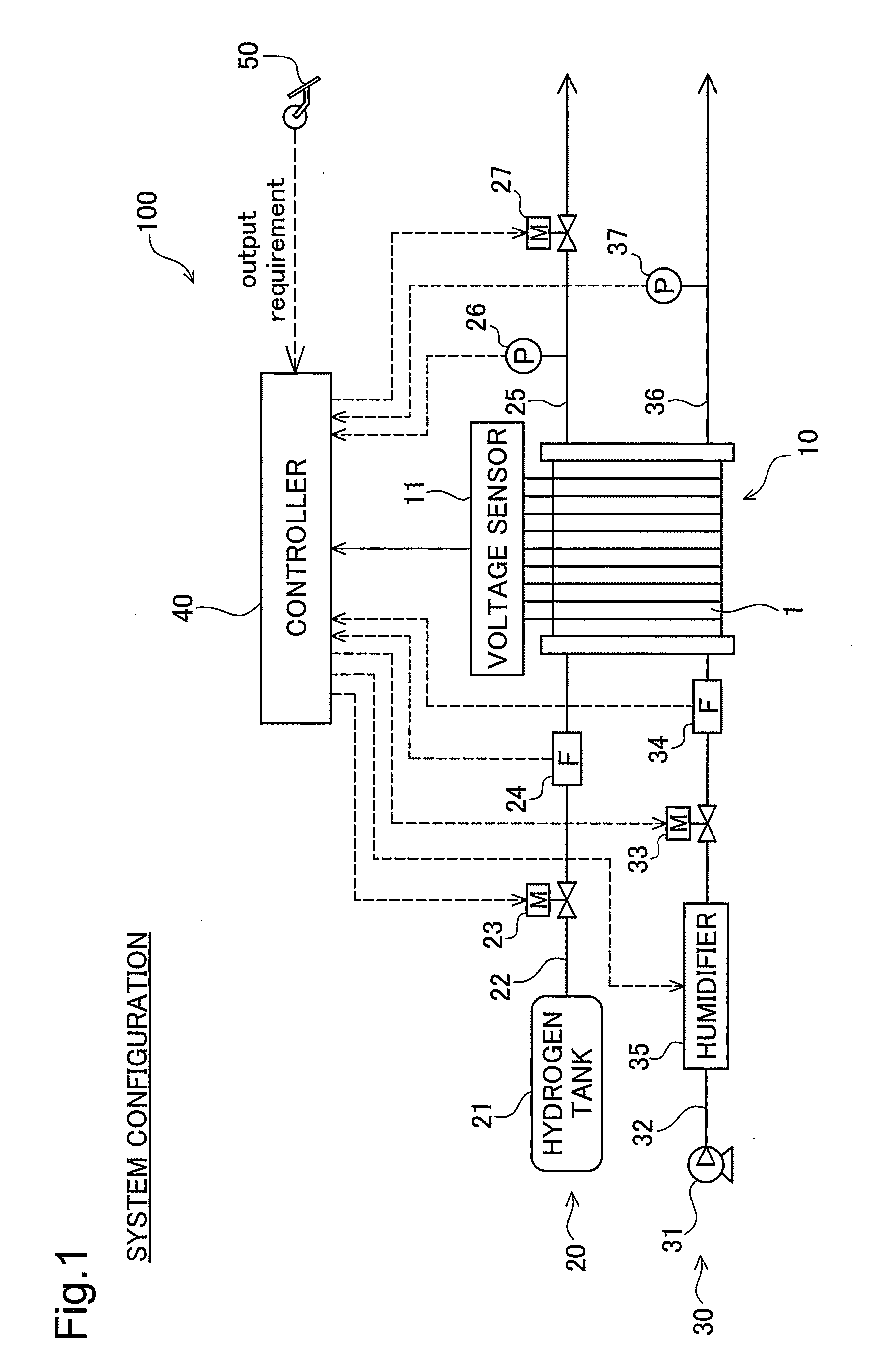
[0024]FIG. 1 is a schematic diagram depicting a configuration of a fuel cell system according to one embodiment of the present invention. This fuel cell system 100 includes a fuel cell stack 10, a hydrogen supply system 20 and an air supply system 30 which are connected to the fuel cell stack 10, and a controller 40.

[0025]The fuel cell stack 10 is a solid polymer fuel cell that is supplied with hydrogen and oxygen, and generates electrical current through an electrochemical reaction between these reactant gases. However, the fuel cell stack 10 need not necessarily be a solid polymer fuel cell, it being possible to implement the invention in any of various kinds of fuel cell.

[0026]The fuel cell stack 10 has a stack structure including a plurality of unit cells 1 each having a power generating element with an electrolyte membrane sandwiched by electrodes. The fuel cell stack 10 is also furnished with a voltage sensor 11 that is adapted to measure potential in each indiv...

modified embodiment 1

B1. Modified Embodiment 1

[0066]In the preceding embodiment, the controller 40 measures the voltage of each individual unit cell 1 and decides to execute the current recovery process depending on these measurements; however, voltage need not be measured for each individual unit cell 1. The current recovery process may instead take place at prescribed timing on an ongoing basis, for example.

embodiment 2

B2. Modified Embodiment 2

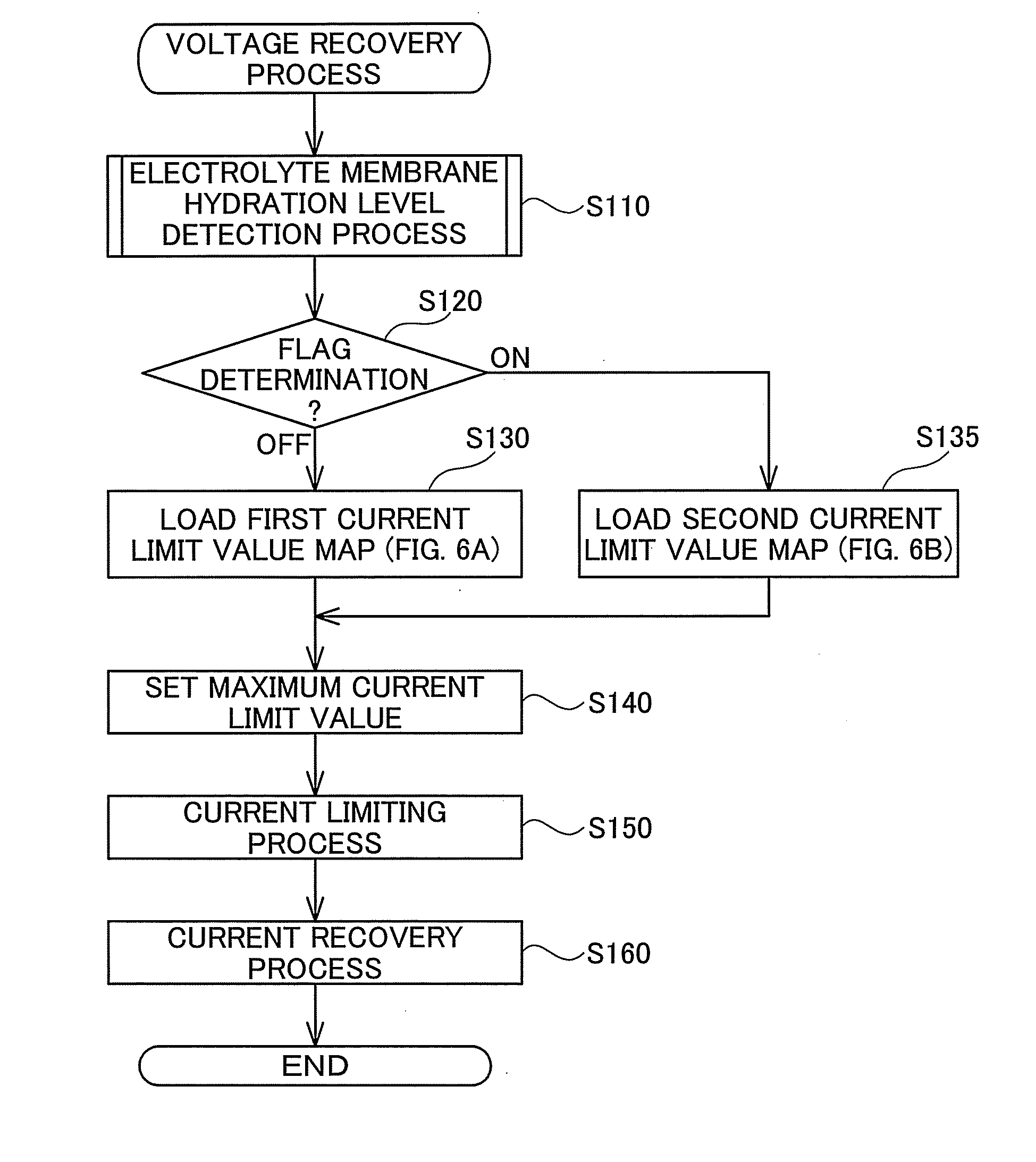
[0067]In the preceding embodiment, by switching between first and second current limit value maps MP1, MP2 according to the Dry flag, the threshold value for the minimum cell voltage (Vm2, Vm4) changes so that if the Dry flag is “ON”, the current limiting process will be triggered under more lenient conditions. However, the condition for triggering the current limiting process need not be set through minimum cell voltage. For example, the current limiting process may be triggered when the extent of increase in FC required power meets or exceeds a certain threshold value. In this case, the controller 40 will progressively lower the threshold value in association with lower hydration levels inside the fuel cell, so that the current limiting process will be triggered under more lenient conditions.


PUM


Abstract

In the event that at least a portion of unit cells in a fuel cell stack have experienced a significant drop in voltage, the fuel cell system will execute a voltage recovery process allowing them to recover generating capability. In the voltage recovery process, a controller measures impedance of the fuel cell stack, and based on these measurements, determines the hydration condition of the electrolyte membrane inside the fuel cell. If, during the determination of hydration condition, the controller has determined that the hydration level is low, a current limiting process for temporarily limiting output of the fuel cell in order to recover generating capability will be triggered under more lenient conditions, as compared to if determined that the hydration level is high.

Description

TECHNICAL FIELD[0001]The present invention relates to a fuel cell system and to a method of controlling the same.BACKGROUND ART[0002]A typical fuel cell has a stacked structure comprising a number of stacked power generating elements (or membrane-electrode assemblies) each having an electrolyte membrane sandwiched by electrodes. Because a fuel cell collects electrical power generated by the individual generating elements and supplies it to an external load, it is desirable that the individual generating elements be able to generate an electrical power in a uniform manner. To this end, there has been proposed recovery processes whereby, if a significant decline in generating capacity of some portion of the generating elements has been detected, the output of the entire fuel cell will be restricted so that this portion of generating elements can recover (see inter alia JP2005-197008A and JP2002-164065A).[0003]It is furthermore desirable in a fuel cell to maintain the electrolyte membr...

Claims


Application Information

Patent Timeline
IPC IPC(8): H01M8/04
CPCH01M8/04492H01M8/04552H01M8/04559Y02E60/50H01M8/0491H01M2008/1095H01M8/04649
Inventor UMAYAHARA, KENJIMAENAKA, TAKESHIIMAI, ATSUSHI
Owner TOYOTA JIDOSHA KK
Why Eureka
Try Eureka