Light-Emitting Diode Illuminating Equipment with High Power and High Heat Dissipation Efficiency

a technology of light-emitting diodes and illuminating equipment, which is applied in the direction of lighting and heating equipment, semiconductor devices for light sources, and support devices for lighting and heating. it can solve the problems of decreased light-emitting efficiency of leds, non-uniform heat-distribution, and inability to raise the brightness of leds, so as to improve heat-dissipation efficiency and improve heat-dissipation efficiency. , the effect o

Inactive Publication Date: 2009-10-01
ENRAYTEK OPTOELECTRONICS
View PDF8 Cites 86 Cited by
  • Summary
  • Abstract
  • Description
  • Claims
  • Application Information

AI Technical Summary

Benefits of technology

[0010]Besides, according to the preferred embodiment, the LED illuminating equipment further includes a heat-isolating ring. The hollow barrel is engaged to the circumference of the heat-dissipating plate device via the heat-isolating ring, so as to isolate the heat conducted to the heat-dissipating plate device to prevent the heat from being conducted to the hollow barrel. By doing so, the LED illuminating equipment will not have a non-uniform heat-distribution, and further the heat-dissipating efficiency can be raised. In addition, the heat-isolating ring can prevent liquid from permeating into the LED illuminating equipment, so the LED illuminating equipment is equipped with water-proof.
[0011]Therefore, according to the embodiment of the invention, the LED illuminating equipment has a better heat-dissipating efficiency, and liquid can be prevented from permeating into the LED illuminating equipment. Accordingly, the LED illuminating equipment of the invention is suitable for a street lighting apparatus.
[0012]The advantage and spirit of the invention may be understood by the following recitations together with the appended drawings.

Problems solved by technology

However, the development of the illuminating equipment mostly focuses on how to control the direction of light to achieve higher brightness, not on how to conduct heat or dissipate heat, as shown in U.S. Pat. No. 6,554,451.
Currently, if the high-power LED continuously lights for a period of time, a problem of over-heat occurs; further, the lighting efficiency of the LED decreases and the brightness of the LED can not be raised.
In addition, when the illuminating equipment is in operation, the traditional illuminating equipment with a number of LEDs generates a problem of non-uniform heat-distribution.
As a result, the LEDs disposed inside the illuminating equipment and exposed under the heat-impact have a decaying opto-electrical efficiency.

Method used


Image

  • Light-Emitting Diode Illuminating Equipment with High Power and High Heat Dissipation Efficiency
  • Light-Emitting Diode Illuminating Equipment with High Power and High Heat Dissipation Efficiency
  • Light-Emitting Diode Illuminating Equipment with High Power and High Heat Dissipation Efficiency

Examples


Embodiment Construction

[0022]A main scope of the invention is to provide a LED illuminating equipment with high power and high heat-dissipating efficiency. According to the invention, the LED illuminating equipment has a structure equipped with water-proof, heat-isolation and uniform heat distribution.

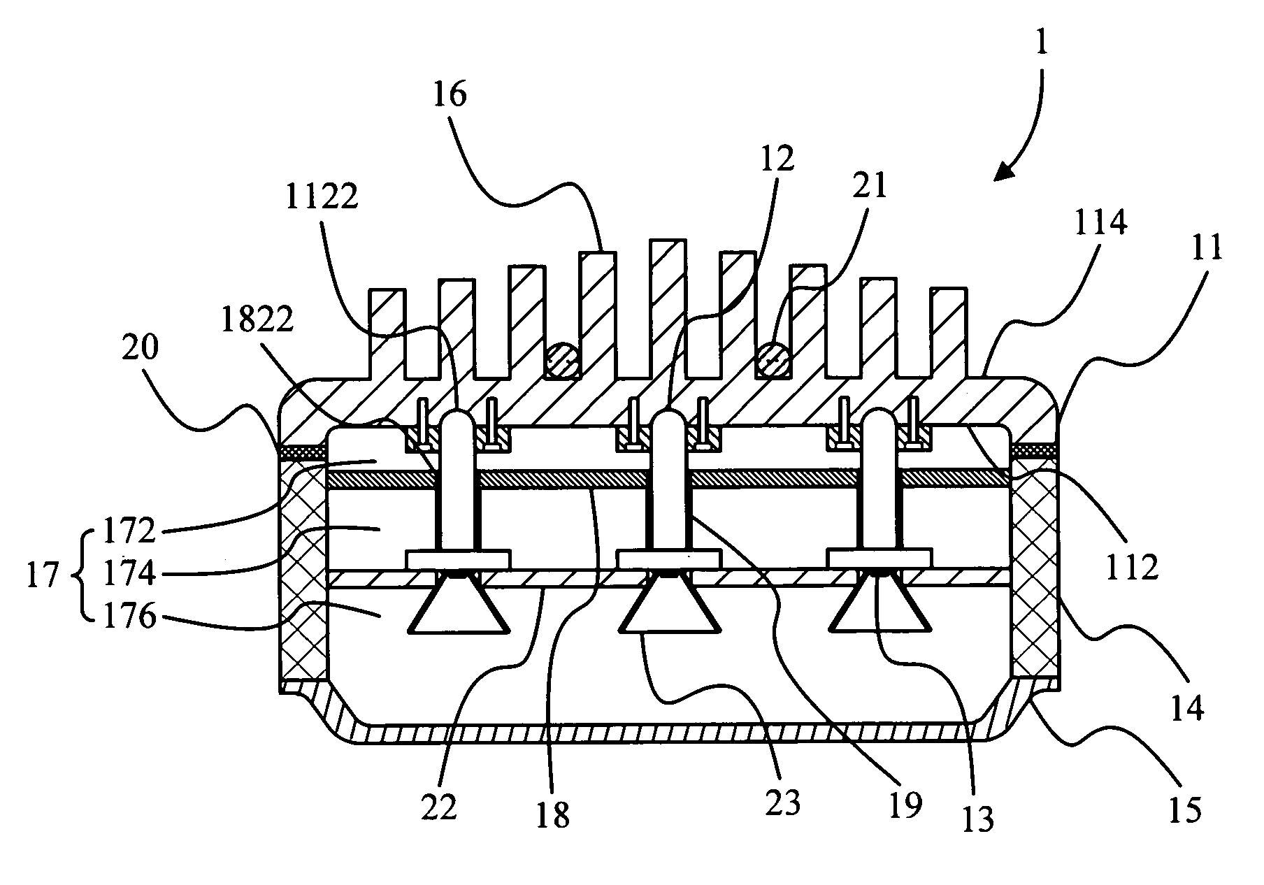
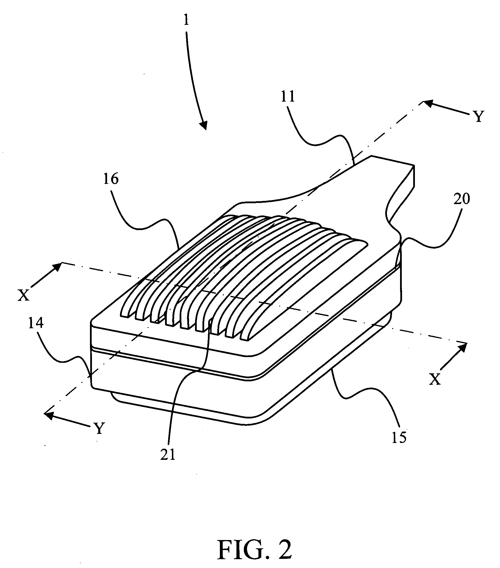
[0023]Please refer to FIG. 2, FIG. 3, FIG. 4A, and FIG. 4B. FIG. 2 is an exterior view of a LED illuminating equipment 1 according to a preferred embodiment of the invention. FIG. 3 is an explosion view of main parts of the LED illuminating equipment 1 according to the preferred embodiment. FIG. 4A is a cross-section view of the LED illuminating equipment 1 shown in FIG. 2 along X-X line. FIG. 4B is a local cross-section view of the LED illuminating equipment 1 shown in FIG. 2 along Y-Y line.

[0024]According to the preferred embodiment of the invention, the LED illuminating equipment 1 includes a heat-dissipating plate device 11, N first heat-conducting devices 12, N diode light-illuminating apparatus 13, a h...


PUM


Abstract

The invention provides a LED illuminating equipment with high power and high heat-dissipating efficiency. The LED illuminating equipment of the invention includes a plurality of diode light-emitting apparatuses. Particularly, the heat generated by the diode light-emitting apparatuses in operation is conducted to a heat-dissipating plate device and the heat-dissipating fins. Besides, the heat is uniformly distributed over the heat-dissipating plate device and further dissipated by the heat-dissipating plate device and the heat-dissipating fins extending thereon.

Description

BACKGROUND OF THE INVENTION[0001]1. Field of the Invention[0002]The invention relates to a light-emitting diode (LED) illuminating equipment, and particularly relates a LED illuminating equipment with high power and high heat-dissipation efficiency, and the LED illuminating equipment has a structure equipped with water-proof, heat-isolation, and uniform heat distribution.[0003]2. Description of the Prior Art[0004]Because LED has advantages of low power consumption, shock-proof, fast response, and suitability for mass production, the research and development of the lighting equipment with the LED is continuously being carried on. Please refer to FIG. 1A and FIG. 1B. FIG. 1A is a front view of an illuminating equipment with a number of LEDs arranged into a matrix. FIG. 1B is a cross-section view of the illuminating equipment shown in FIG. 1A along W-W line. As shown in FIG. 1A and FIG. 1B, the illuminating equipment provides brighter illumination by a number of LEDs arranged into a ma...

Claims


Application Information

Patent Timeline
Patent Type & Authority Applications(United States)
IPC IPC(8): F21S4/00F21V29/15F21Y101/00
CPCF21V29/004F21W2131/103F21Y2101/02F21V29/763F21V29/006F21V29/75F21Y2105/001F21Y2105/10F21Y2115/10F21V29/71F21V29/51F21K9/60Y02B20/72
Inventor CHEN, JEN-SHYAN
Owner ENRAYTEK OPTOELECTRONICS
Why Eureka
Try Eureka