Ultra low frequency acoustic vector sensor

a vector sensor and ultra low frequency technology, applied in the direction of liquid/fluent solid measurement, mechanical vibration separation, instruments, etc., can solve the problems of increasing the difficulty of developing a highly sensitive, low-noise vector sensor in a small, neutrally buoyant package, and becoming even more challenging in the ultra low frequency rang

Active Publication Date: 2009-10-01
STEVENS INSTITUTE OF TECHNOLOGY
View PDF5 Cites 7 Cited by
  • Summary
  • Abstract
  • Description
  • Claims
  • Application Information

AI Technical Summary

Benefits of technology

[0006]The problems and disadvantages associated with the prior art are overcome by the present invention, which includes an low frequency acoustic vector sensor for measuring acoustic wave particle velocities in a liquid, such as water. The acoustic vector sensor includes a housing, a horn positioned within the housing for amplifying the acoustic wave particle velocities, and a buoyant object positioned within the horn. The buoyant object is moveable between a stationary position and a displaced position in response to the amplified acoustic

Problems solved by technology

Developing a highly sensitive, low-noise vector sensor in a small, neutrally buoyant package is extremely challenging.
It becomes even more challenging for the ultra low frequency range.
One reason accelerometers used in conventional sensors are not suitable for sensitive measurements at ultra low frequencies is that acceleration is proportional to f*v, where v is

Method used


Image

  • Ultra low frequency acoustic vector sensor
  • Ultra low frequency acoustic vector sensor
  • Ultra low frequency acoustic vector sensor

Examples


Embodiment Construction

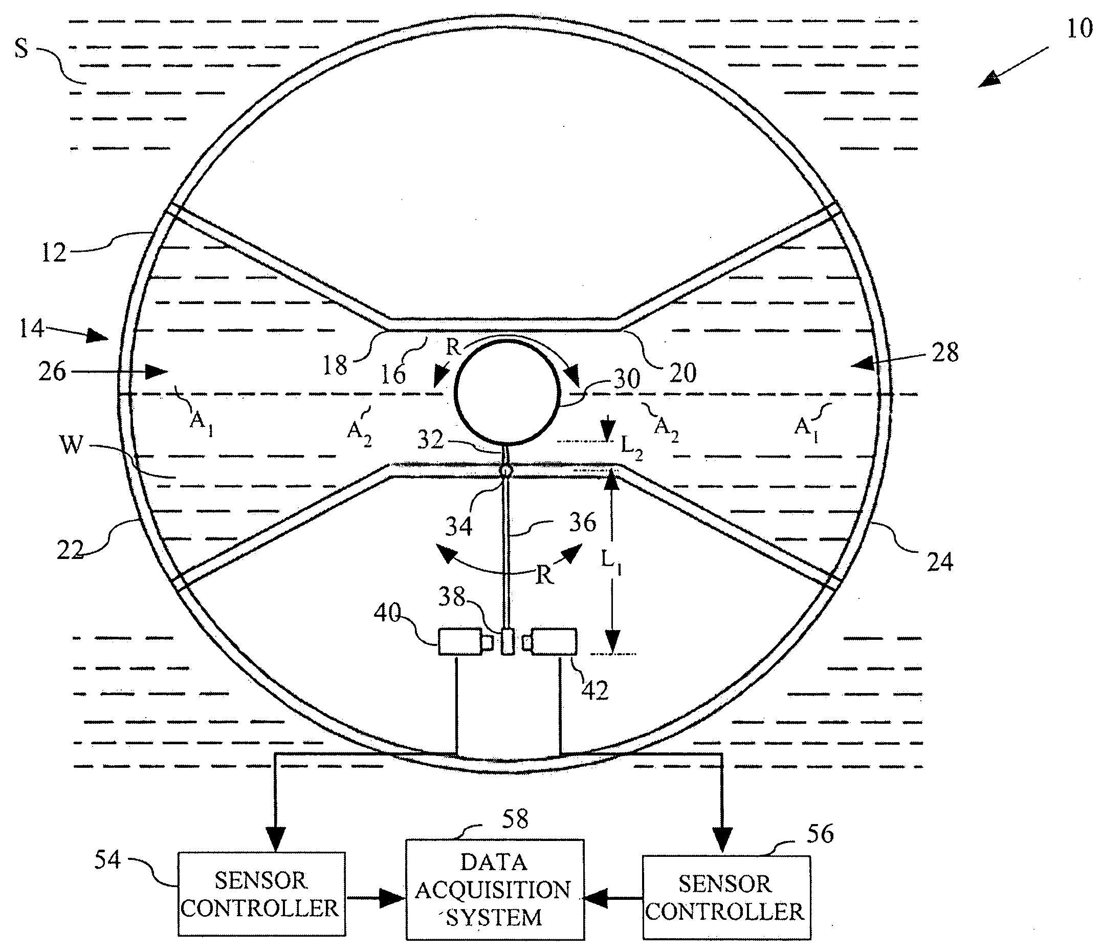
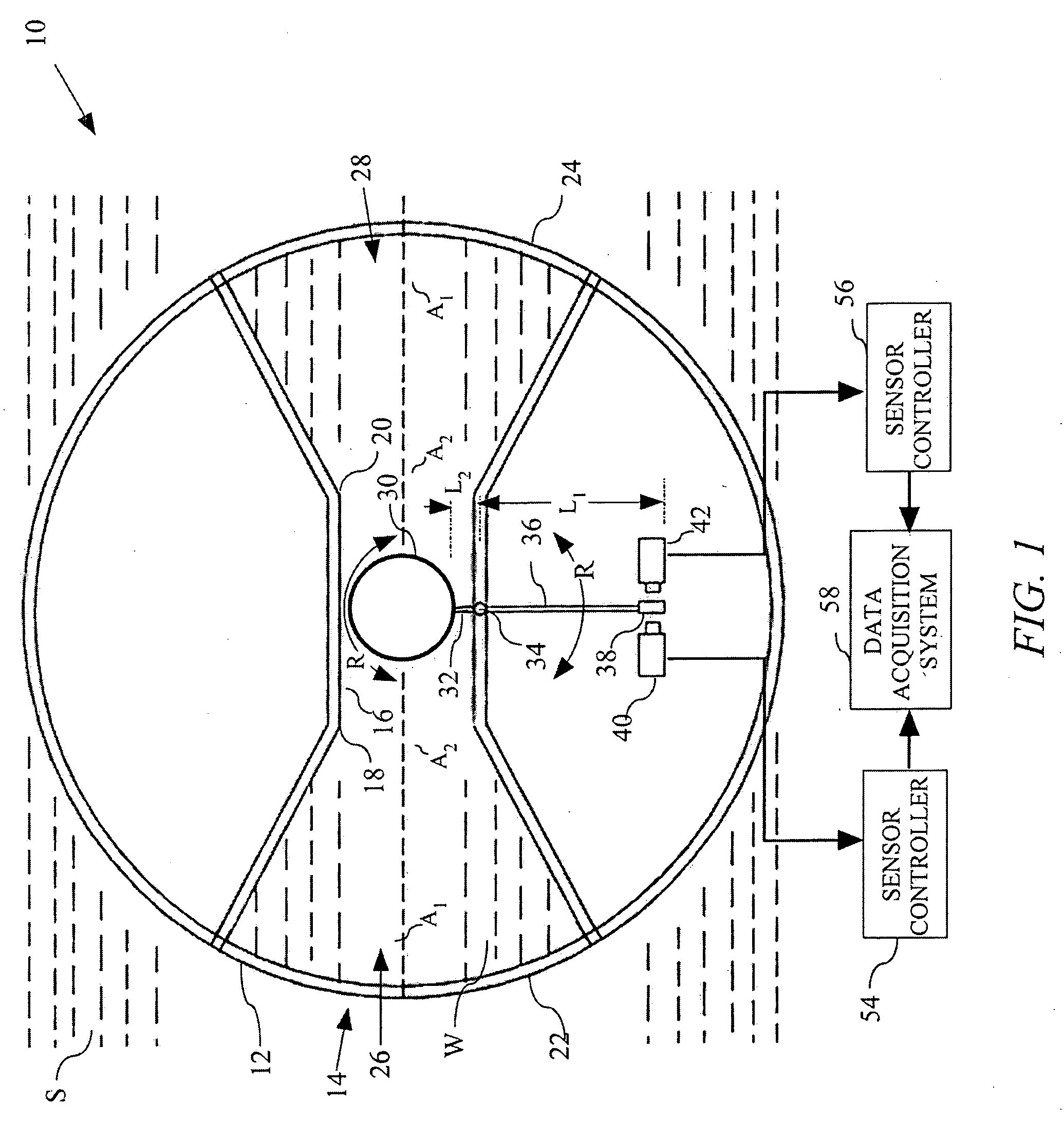
[0013]FIG. 1 illustrates an ultra low frequency acoustic vector sensor (herein “the acoustic sensor”) 10 constructed in accordance with an exemplary embodiment of the present invention. The acoustic sensor 10 is adapted to measure ultra low frequency liquid particle oscillations when positioned in a body of water S (e.g., a sea or lake). More particularly, the acoustic sensor 10 includes a spherically-shaped housing 12 which has a liquid-tight compartment or horn 14 positioned centrally therein. The horn 14 is shaped in the form of an axis-symmetrical body of revolution having its longitudinal axis coincident with a diameter of the housing 12. A tube 16 having openings 18, 20 is centrally positioned in the horn 14. Sound transparent membranes or screens 22, 24 are located at opposite ends of the horn 14 for allowing acoustic wave oscillations (not shown) to enter and leave the horn 14, while preventing water S from entering the horn 14.

[0014]A frustoconically shaped section 26 of th...


PUM


Abstract

An acoustic vector sensor mounted in a housing is provided for measuring ultra low frequency acoustic wave particle velocities in a liquid, comprising a horn for amplifying the acoustic wave particle velocities, and a neutrally buoyant object supported in a liquid contained in the horn. The neutrally buoyant object, in reacting to the amplified acoustic wave particle velocities, produces displacements that are sensitively measured.

Description

CROSS-REFERENCE TO RELATED APPLICATIONS[0001]The present application is a Section 111(a) application relating to commonly owned, co-pending U.S. Provisional Patent Application Ser. No. 61 / 072,481, filed Mar. 31, 2008, the disclosure of which is incorporated herein by reference in its entirety.FIELD OF THE INVENTION[0002]The present invention relates to underwater acoustic measurement devices, and, more particularly, to underwater acoustic measurement devices related to seismic exploration, underwater surveillance (detection of divers, submarines, torpedoes, etc.), tsunami and seismic activity monitoring, and other similar activities.BACKGROUND OF THE INVENTION[0003]Traditional underwater acoustic sensors are pressure sensors (e.g., hydrophones) responsive to oscillating pressure in the field of the acoustic wave. Pressure is a scalar quantity, so a single hydrophone (smaller than the acoustic wavelength) has no directionality. Unlike hydrophones, vector sensors are responsive to wat...

Claims


Application Information

Patent Timeline
IPC IPC(8): G10K11/00
CPCG01P5/02G01H3/00
Inventor DONSKOY, DIMITRISEDUNOV, NIKOLAY
Owner STEVENS INSTITUTE OF TECHNOLOGY
Why Eureka
Try Eureka