Radio base station, user device, and method used in mobile communication system

a mobile communication system and radio base station technology, applied in the direction of electrical equipment, data switching by path configuration, wireless commuication services, etc., can solve the problems of difficult to improve the quality of control channels, and achieve the effect of preventing or reducing the complication of communication device configuration, signal processing, and product testing processes

Active Publication Date: 2009-10-01
NTT DOCOMO INC
View PDF21 Cites 93 Cited by
  • Summary
  • Abstract
  • Description
  • Claims
  • Application Information

AI Technical Summary

Benefits of technology

[0010]An aspect of the present invention makes it possible to prevent or at least reduce the complication of communication device configurations, signal processing, and product testing processes that may occur due to the use of multiple TTIs.

Problems solved by technology

Unlike data channels, it is difficult to improve the quality of control channels by techniques such as retransmission control and adaptive modulation and coding (AMC).

Method used


Image

  • Radio base station, user device, and method used in mobile communication system
  • Radio base station, user device, and method used in mobile communication system
  • Radio base station, user device, and method used in mobile communication system

Examples


first embodiment

Base Station—Downlink

[0051]FIG. 3 is a partial block diagram illustrating a functional configuration of a base station according to an embodiment of the present invention. FIG. 3 mainly shows functional components or entities related to downlink scheduling. As shown in FIG. 3, the base station includes buffers 1 through N, a downlink resource allocation unit 32, downlink L1 / L2 control channel transmission power calculation units 1 through N, a coverage determining unit 34, an uplink L1 / L2 control channel transmission cycle control unit 36, and a downlink signal generating unit 38 including a shared data channel generating unit 382 and an L1 / L2 control channel generating unit 384.

[0052]Each of the buffers 1 through N temporarily stores transmission data (downlink transmission data) to be transmitted to the corresponding one of terminals 1 through N and sends the downlink resource allocation unit 32 information regarding the amount of buffered data to be transmitted. Here, “terminals”...

second embodiment

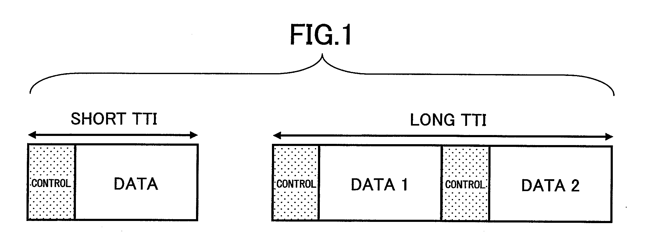
[0100]As described above, using TTIs having different lengths may complicate signal processing. However, this problem may be reduced by appropriately scheduling packets with different TTIs.

[0101]FIG. 17 is a drawing illustrating an example of uplink radio resource allocation. In FIG. 17, a first resource block using a long TTI (2.0 ms) and having a narrow bandwidth and a second resource block using a short TTI (0.5 ms) and having a wide bandwidth are provided. For example, the first resource block is allocated to a user device whose channel conditions are expected to be comparatively poor and the second resource block is allocated to a user device whose channel conditions are expected to be comparatively good. The channel conditions of user devices can be estimated at the base station based, for example, on uplink CQIs and path losses. The CQI may be represented by the reception quality of a reference signal (pilot channel) received at the base station.

[0102]In this example, the fir...


PUM


Abstract

A radio base station used in a mobile communication system is disclosed. The radio base station includes a scheduler configured to allocate one or more resource blocks, which are defined by a predetermined bandwidth and a predetermined transmission time interval, to a user device; and a reporting unit configured to report scheduling information indicating radio resource allocation to the user device. The scheduler is configured to generate the scheduling information such that downlink data channels and downlink control channels are transmitted using the transmission time interval as a transmission unit and uplink control channels are transmitted using an integral multiple of the transmission time interval as a transmission unit.

Description

TECHNICAL FIELD[0001]The present invention generally relates to a radio base station, a user device, and a method used in a mobile communication system.BACKGROUND ART[0002]In the field of mobile communication, research and development of next generation mobile communication systems are being conducted at a rapid pace. In such mobile communication systems, signals are transmitted as packets in unit transmission periods called transmission time intervals (TTIs). The transmission time interval (TTI) may also be called a time period or a subframe. The TTI is used as a base unit of various types of signal processing such as radio resource allocation, channel coding, and retransmission.[0003]Meanwhile, a period of time from when a data channel including user data is transmitted from a sending end to a receiving end where the data channel is demodulated and decoded until when the sending end receives delivery confirmation information (acknowledge or negative acknowledge) from the receiving...

Claims


Application Information

Patent Timeline
Patent Type & Authority Applications(United States)
IPC IPC(8): H04W72/04H04L47/20H04L47/22H04W72/12
CPCH04L47/10H04L47/14H04L47/20H04W72/1263H04L47/2433H04W72/1231H04W72/0446H04L47/22H04W72/542H04L12/28H04W72/12H04W8/04
Inventor HIGUCHI, KENICHIKISHIYAMA, YOSHIHISASAWAHASHI, MAMORU
Owner NTT DOCOMO INC
Why Eureka
Try Eureka