
Optical Display Device

a display device and optical technology, applied in the field of optical display devices, can solve the problems of inconvenient use of plane-plate hmds, inability to meet the needs of plane-plate hmds, and relatively high production costs, and achieve the highest possible diffraction efficiency, simple and economical production

Active Publication Date: 2009-10-01
CARL ZEISS JENA GMBH
View PDF10 Cites 89 Cited by
  • Summary
  • Abstract
  • Description
  • Claims
  • Application Information

AI Technical Summary

Benefits of technology

[0011]It is therefore an object of the invention to provide such an optical display device with which the light can both be coupled into the plane plate of the light guide with the highest possible diffraction efficiency by the input grating and coupled out again homogeneously by the output grating. The optical display device should furthermore be simple and economical to produce.
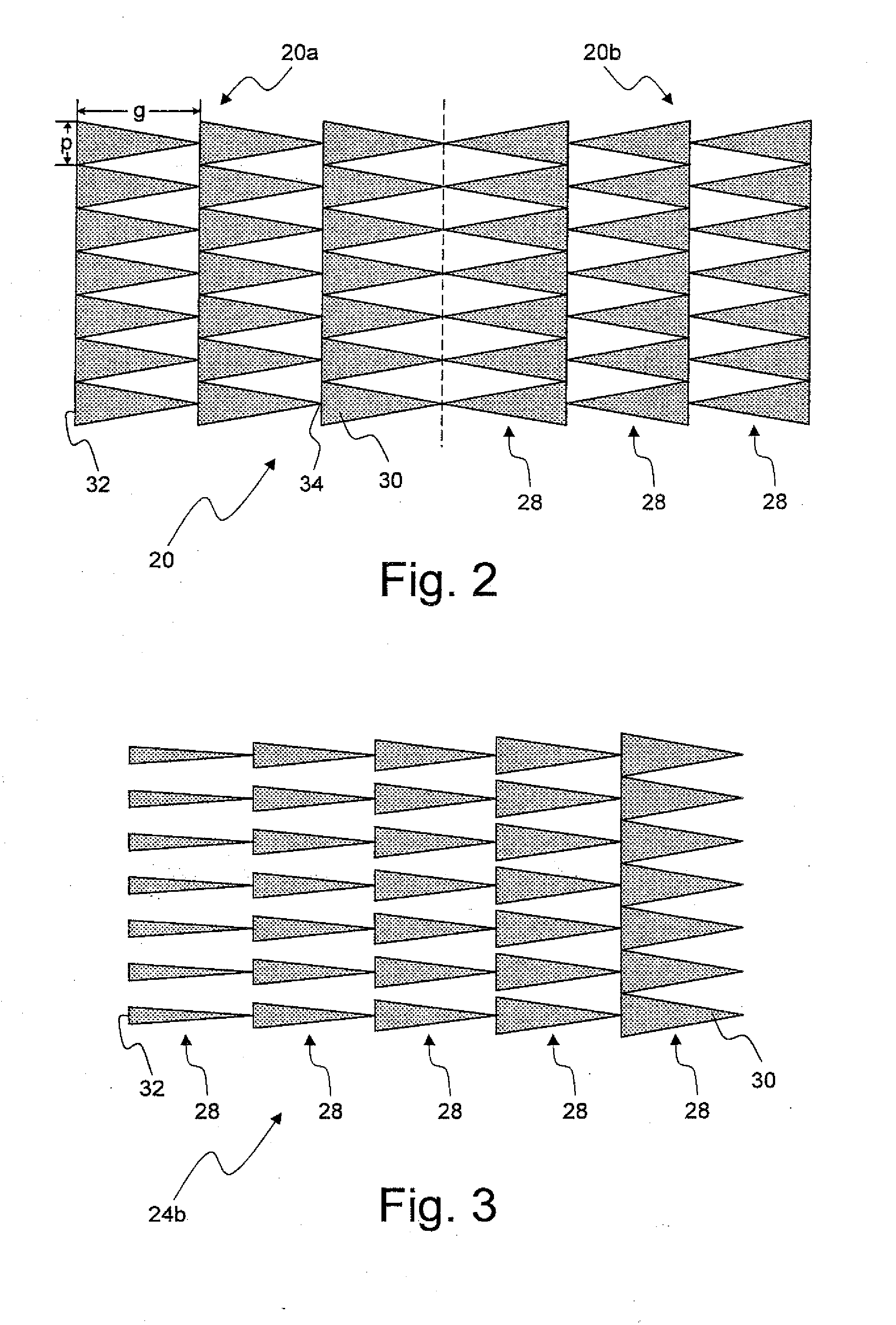
[0013]Since the gratings specified in the claims, referred to below as BLACES gratings, have a diffraction efficiency of between 65% and 75% over a large incidence range, they are very suitable for coupling light into a plane plate. A particular advantage is that BLACES gratings can be produced very simply compared with oblique gratings.

Problems solved by technology

Owing to shadowing effects, which occur with the small grating widths that are required in order to achieve the strong deviation, conventional blaze gratings are unsuitable for use in plane-plate HMDs.
Binary gratings, which have an input and output efficiency of at best 30 per cent, are likewise not an optimal solution.
So-called oblique gratings have therefore hitherto been used, although these are relatively expensive to produce.

Method used


Image

  • Optical Display Device
  • Optical Display Device
  • Optical Display Device

Examples


Embodiment Construction

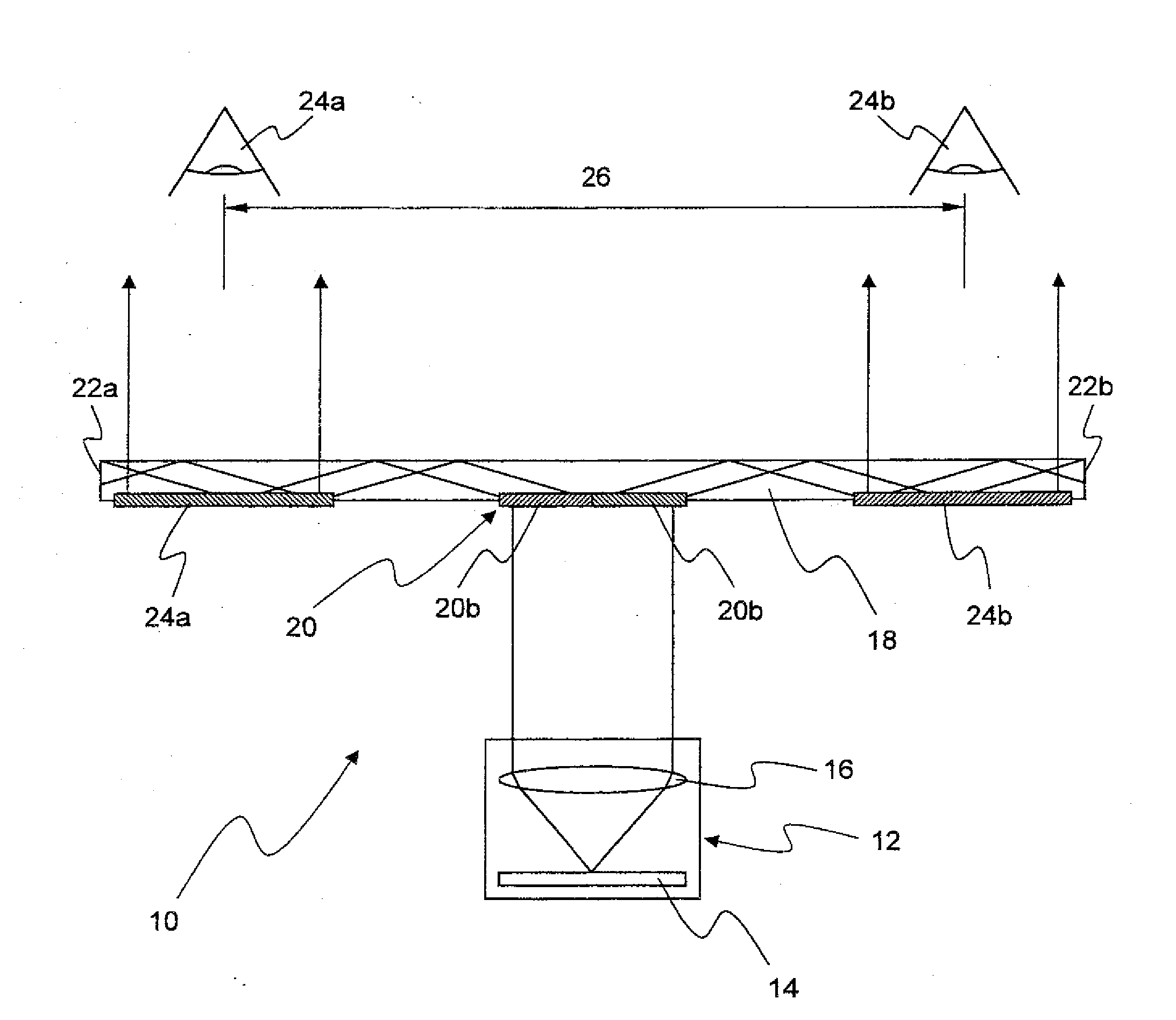
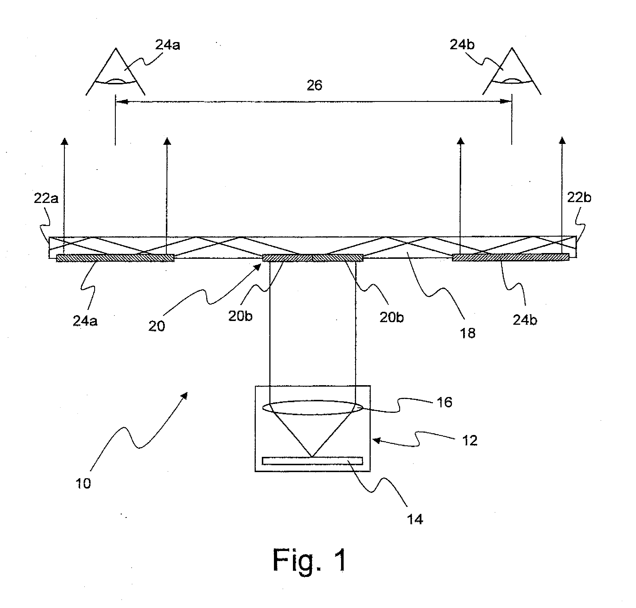
[0020]FIG. 1 shows an optical display device 10 in a highly schematised representation, which may be used for example in so-called head-mounted or head-up displays. The optical display device 10 comprises a micro-display 12, which directs the image of an image-generating system 14 through optics 16 onto the middle of a flat side of an essentially plane-parallel plate 18. The imaging system 14 may, for example, be provided by a liquid-crystal display (LCD) or by arrangements of light-emitting diodes (LEDs) or organic light-emitting diodes (OLEDs), such as are known from in particular from the field of entertainment electronics.

[0021]The light generated by the image-generating system 14 then strikes a grating 20 applied in or on the plane-parallel plate 18, which couples the light into the plane-parallel plate 18 by means of diffraction along it. The grating constant g of the grating 20 is selected so that the light is coupled into the plane-parallel plate 18 at an angle which is grea...


PUM


Abstract

An optical display device, in particular for use in a head-up display or a head-mounted display, comprises an essentially planar light guide, an image-generating system, a first diffraction grating by which light that comes from the image-generating system can be coupled into the light guide, and a second diffraction grating, by which the light can be coupled out again from the light guide. At least one of the two diffraction gratings is a binary-blazed grating having a multiplicity of diffraction structures, which are composed of a multiplicity of individual substructures that ensure a blaze effect and in plan view have the shape of a closed geometrical surface.

Description

RELATED APPLICATION DATA[0001]This patent is based on German patent application 10 2008 005 817.3 filed Jan. 24, 2008. This patent claims priority benefit of this prior filed German application, which is hereby incorporated by reference in its entirety.BACKGROUND OF THE INVENTION[0002]1. Field of the Invention[0003]The invention relates to an optical display device which is suitable in particular for use in a head-up display or a head-mounted display, such as are known for example from entertainment electronics, in order to increase the exit pupil of an image-generating system by means of diffractive elements.[0004]2. Description of the Prior Art[0005]Currently, in the field of man-machine interfaces, principles and devices are increasingly being developed by which computer-enhanced information of the real experiential world can be transmitted to humans. So-called augmented or virtual reality displays (VRD) are an example of this. Such displays, which may for example be configured s...

Claims


Application Information

Patent Timeline
Patent Type & Authority Applications(United States)
IPC IPC(8): G02B6/34
CPCG02B5/1861G02B5/1866G02B6/0016G02B6/0038G02B2027/0136G02B27/0101G02B27/0172G02B2027/0118G02B6/34G02B27/4272
Inventor KLEEMANN, BERND
Owner CARL ZEISS JENA GMBH
Learn More