Tampon package and method for making the same

a technology of tampons and packages, applied in the field of tampons packages, can solve the problems of increasing the ejection force needed to expel, undesirable for the tampon pledget to prematurely expand (e.g., bloom) within the applicator barrel, and generally intended to be relatively minimal, so as to achieve the effect of increasing the ejection for

Inactive Publication Date: 2009-10-01
EVEREADY BATTERY CO INC
View PDF15 Cites 22 Cited by
  • Summary
  • Abstract
  • Description
  • Claims
  • Application Information

AI Technical Summary

Benefits of technology

[0025]Some of the advantages of the tampon package 18 constructed and operating in accordance with the present invention are demonstrated by the following studies of existing tampon packages as well as comparisons of the inventive tampon packages to these conventional packages.
[0026]For testing purposes, aging is often simulated by purposefully subjecting tampon assemblies to specific conditions of temperature and humidity for specified periods of time. It has been found that aging, particularly aging under humid ambient conditions, can cause an increase in the ejection force needed to dispense the tampon from the applicator barrel.

Problems solved by technology

However, the ejection force is generally intended to be relatively minimal to permit ease of use.
As can be appreciated, it is undesirable for the tampon pledget to prematurely expand (e.g., bloom) within the applicator barrel.
Premature expansion of the tampon pledget within the barrel results in an increase in ejection force needed to expel the at least partially expanded tampon pledget from the applicator barrel.
As such, a significant increase in the needed ejection force may result if a tampon pledget is exposed to moisture for a prolonged period of time.
As can be appreciated, any significant increase in the ejection force needed to expel a tampon pledget from an applicator barrel is undesirable.

Method used


Image

  • Tampon package and method for making the same
  • Tampon package and method for making the same
  • Tampon package and method for making the same

Examples


example 1

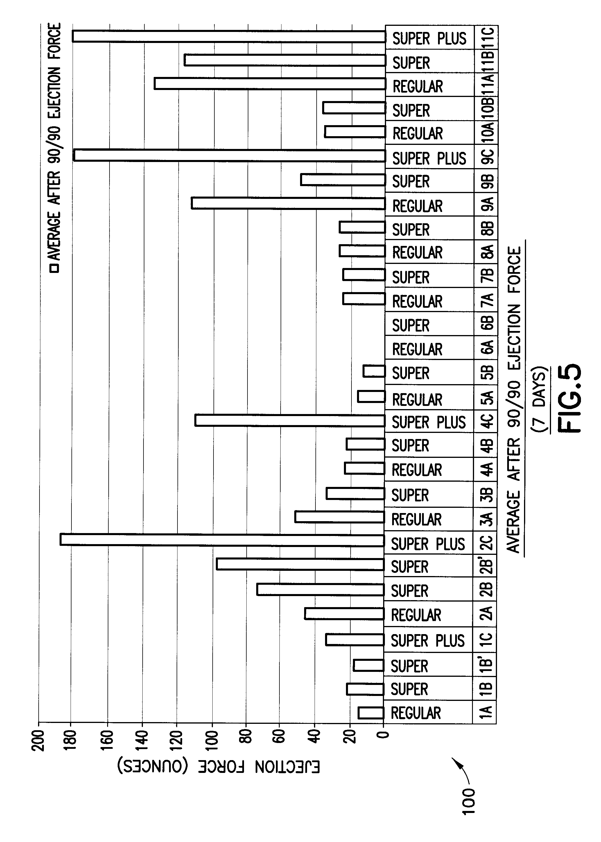
[0027]In a first example, results 100 of which are illustrated in FIG. 5, a variety of conventional un-wrapped tampon assemblies were subjected to an aging cycle of ninety degrees Fahrenheit (90° F.) and ninety percent (90%) relative humidity for seven (7) days. At the end of the aging cycle, the tampon assemblies were tested to determine the force required to eject the tampon pledgets from corresponding applicator barrels. The results 100 of the test, indicating required ejection force, ranged from about forty to about one hundred eighty ounces (40 to 180 oz.). As shown, there was a large increase in ejection force of the aged tampon assemblies versus new, unexposed tampon assemblies, for which an ejection force of in a range of ten to sixty ounces (10 to 60 oz.) is typically preferred.

[0028]Evaluation of the results 100 of the aging cycle depicted in FIG. 5 indicates that tampon pledgets bloom (e.g., radially expand) prematurely in the applicator barrels as a result of the absorpt...

example 2

[0035]In a second exemplary analysis, the inventors wrapped a third set of tampon assemblies including tampon pledgets rated “regular” absorbency in wrappers comprising the production wrap of Example 1. In this analysis, the tampon assemblies were exposed to a longer period of aging. For example, the third tampon assembly packages were subjected to an aging cycle of seven (7) days at seventy-eight degrees Fahrenheit (78° F.) and seventy-five percent (75%) relative humidity (RH). After this prolonged aging cycle, the ejection forces of the third tampon assemblies and other measurements were made, as described above. The results are set forth in the following Table 2A.

TABLE 2AProduction Wrap“Regular” Absorbency TamponsConditions: 78° F. / 75% RH, in chamber for 7 daysEjection Forces and AbsorbencyEjectionDryWetGram perForceWeightWeightAbsorbencygram(ounces)(grams)(grams)(grams)absorbencyNumber83333of SamplesAverage26.471.849.848.003.74Std. Dev.1.56970.07230.40140.32920.0112Maximum29.041...

example 3

[0040]A fifth set of tampon assemblies including tampon pledgets rated “regular” absorbency were placed in production wrappers, as described in Example 1. The fifth set of tampon packages were then subjected to an aging cycle of seven (7) days at ninety degrees Fahrenheit (90° F.) and ninety percent (90%) relative humidity (RH). After this prolonged and more humid aging cycle, the ejection forces of the fifth set of tampon assemblies and other measurements were made, as described above. The results are set forth in the following Table 3A.

TABLE 3AProduction Wrapper“Regular” Absorbency TamponsConditions: 90° F. / 90% RH, in chamber for 7 daysEjection Forces and AbsorbencyEjectionDryWetGram perForceWeightWeightAbsorbencygram(ounces)(grams)(grams)(grams)absorbencyNumber83333of SamplesAverage36.061.869.577.713.57Std. Dev.3.46380.04300.14140.09880.0382Maximum42.411.909.707.803.60ResultMinimum32.271.829.427.613.53Result

[0041]As illustrated in Table 3A, the average ejection force of the fifth...


PUM

PropertyMeasurementUnit
thicknessaaaaaaaaaa
thicknessaaaaaaaaaa
thickaaaaaaaaaa

Abstract

A tampon package includes a tampon assembly sealed within packaging material. The packaging material is continuously sealed about its perimeter to form an internal air-tight chamber for retaining the tampon assembly therein. The tampon package includes a tampon pledget disposed within an applicator barrel. In one embodiment, the packaging material is made from a water-barrier material. The water-barrier material may be a laminate of polyolefin or polyethylene terephthalate and an ethylene vinyl acetate material.

Description

BACKGROUND OF THE INVENTION[0001]1. Field of the Invention.[0002]This invention relates generally to tampons packages and, more particularly, to tampon packages having a continuous perimeter seal enclosing a tampon assembly within an air, moisture and contaminate resistance wrapper.[0003]2. Description of Related Art.[0004]Generally speaking, a tampon pledget is commonly sold as part of a tampon assembly that includes the tampon pledget and an applicator in which the tampon pledget is disposed. The applicator typically includes an applicator barrel that retains the tampon pledget therein and a plunger for ejecting the tampon pledget from the applicator barrel. Tampon assemblies vary with regard to a force required for a user to eject the tampon pledget from the applicator barrel. However, the ejection force is generally intended to be relatively minimal to permit ease of use.[0005]Tampon assemblies are commonly packaged individually in an overwrap (hereinafter simply “wrapper”). Con...

Claims


Application Information

Patent Timeline
Patent Type & Authority Applications(United States)
IPC IPC(8): A61F13/20A61B19/02
CPCA61F13/55185B65D75/58B65D75/20A61F15/003A61F13/20
Inventor GLAUG, FRANK S.EDGETT, KEITH J.DOUGHERTY, JR., EUGENE P.TACKETT, DOUGLAS L.
Owner EVEREADY BATTERY CO INC
Why Eureka
Try Eureka