Multi-joint structure, mounting tool using it, system and human machine interface

Inactive Publication Date: 2009-10-01
KYOKKO ELECTRIC
View PDF15 Cites 68 Cited by
  • Summary
  • Abstract
  • Description
  • Claims
  • Application Information

AI Technical Summary

Benefits of technology

[0092]The multi-joint structure of the present invention has the following effects. The multi-joint structure automatically or manually enables the separation and the connection of every 1 piece or several. The multi-joint structure can be connected with the multistep by using one connected divergence means or more. As a result, positional identification by the cooperation of a cable technology and a wireless technology and the automatic authentication of self-ID become possible.
[0093]Moreover, the multi-joint structure of the present invention can be used by being installed in the human body as a sensor that detects the movement of the human body and fingers. For instance, the mounting tool using the multi-joint struct

Problems solved by technology

Conventionally, a complex expensive means was used.
However, the length of the multi-joint structure was too long compared with a necessary amount of the object, too short, and application was difficult.
This is the 1st problem of conventional technology.
In addition, the divergence means cannot not be transformed and be driven autonomous.
This is the 2nd problem of conventional technology.
Moreover, when the disaster such as the large-scale earthquakes occurs, prompt life rescue work is needed.
In the building in which it is struck (subway, underground shopping center, a

Method used


Image

  • Multi-joint structure, mounting tool using it, system and human machine interface
  • Multi-joint structure, mounting tool using it, system and human machine interface
  • Multi-joint structure, mounting tool using it, system and human machine interface

Examples


Example

Embodiment 1

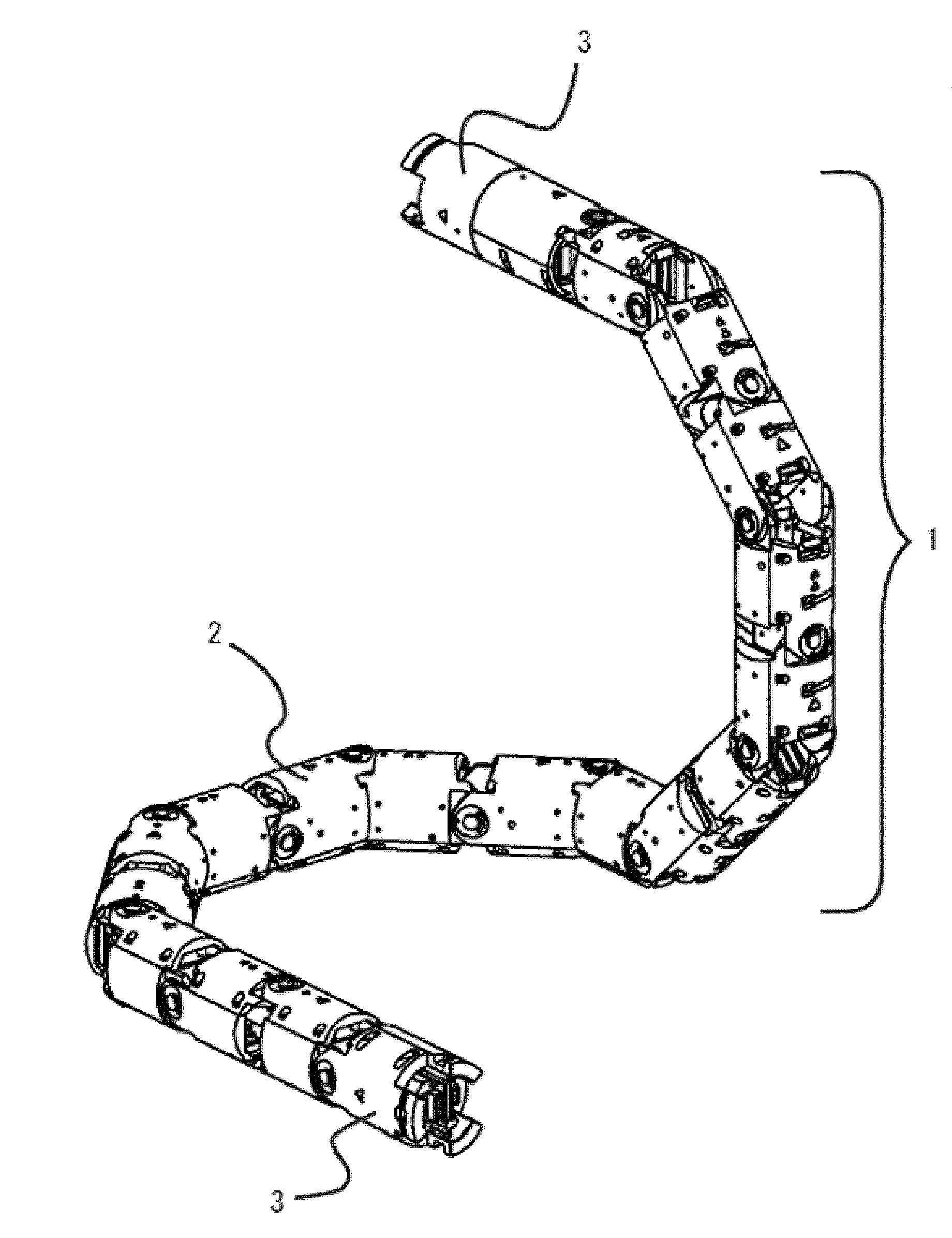
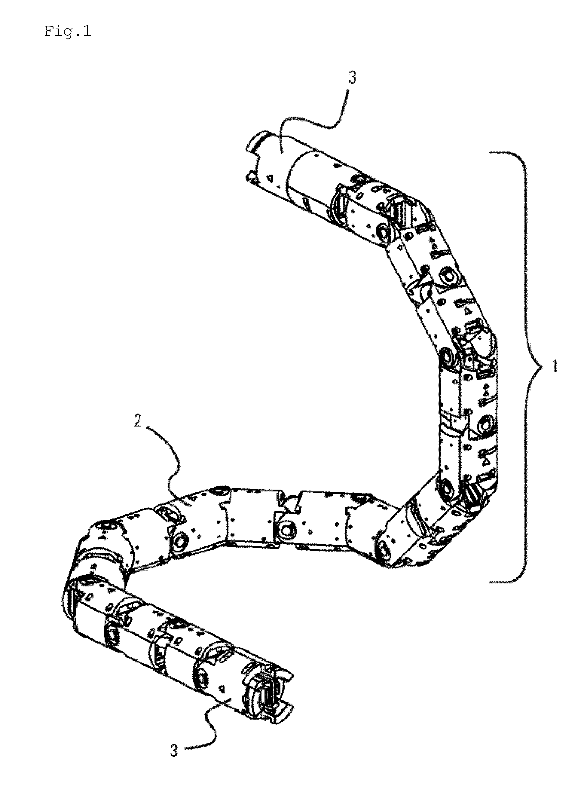
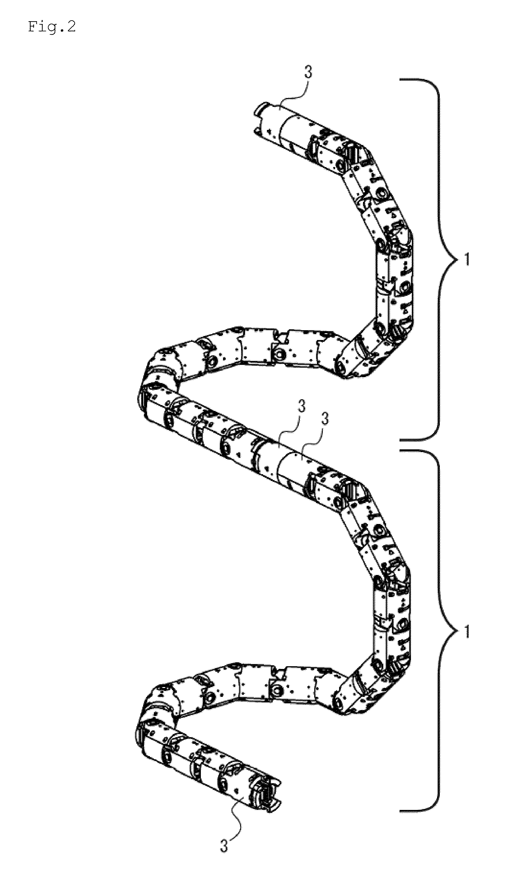
[0120]FIG. 1 is whole of multi-joint structure (Hereafter, it is called FST) according to the present invention perspective view. FIG. 2 is perspective view in the state that two FST combined intuition. FST 1 assumes joint unit 2 to be a minimum unit, and is a structure of the tube shape composed of plural joint units. Movable between each joint units in free. Each FST connects the joint unit at both ends with other FST as connected joint unit 3. As a result, the multi-joint structure to which a lot of joint units range can be composed. As for the moving part of each joint unit, the potentiometer of the change of the change of the opposing angle of the joint unit, the change of the distance, and the axis rotation (Twist) for the change amount detection has been installed. CPU board is set in ten joint units at one rate. Moreover, the arithmetic unit of processing of one FST as a whole has been installed. The electric wire has been installed in the structure of the tube s...


PUM


Abstract

To manually and optionally change length of a multi-joint structure, the multi-joint structure of the present invention is constituted so that variation detection sensor such as potentiometers is provided on connecting parts between each of joints, one or a plurality of the sensors are assumed to be a unit of the group, the signals of the sensors are captured by signal processing parts in each unit of the group, the parts between the signal processing parts are connected to the communication network and the signal processing part connected to the communication network computes and processes in accordance with signal data of the sensors, and it is constituted to output moving quantity and vector when the joints move to translate and rotate by detecting variation of the connecting parts between the joints at real time when shape of the multi-joint structure is deformed.

Description

BACKGROUND OF THE INVENTION[0001]The present invention is a technology concerning the recognition means to install the multi-joint structure that connects or separates one joint unit or more and is composed in the life, the robot, and the machine, etc., and to identify the position, movement, and shape, etc.[0002]Moreover, the technology of the multi-joint structure automatically or manually that enables the separation and the connection of every 1 piece or several.[0003]The present invention is a technology that recognizes the position of the hand, the foot, and the head of the human body by assuming that the multi-joint structure can be connected with the multistep by using one connected divergence means or more.[0004]Moreover, the present invention is a technology that enables the extension, development in respect, and development with the mesh structure, etc. by assuming the multi-joint structure to be able to connect multi steps by using one connected divergence means or more. ...

Claims


Application Information

Patent Timeline
IPC IPC(8): G06F19/00B25J11/00
CPCA61B1/0055G06F3/014A61B5/447A61B5/6887A61B5/6892A61B2562/02A61H1/0237A61H1/0274B08B9/045B25J5/005B25J9/0006B25J9/06B25J9/065B62D55/0655B62D55/075B62D57/024G06F3/011A61B1/31
Inventor OSUKA, KOICHINAKAGAWA, SHINOBUWADA, TAKASHIKITADA, YASUTERUKUSUNOKI, KENJI
Owner KYOKKO ELECTRIC
Why Eureka
Try Eureka