Fluid control systems employing compliant electroactive materials

a technology of electroactive materials and fluid control systems, which is applied in the direction of valve operating means/release devices, machines/engines, non-mechanical valves, etc., can solve the problems of reducing the overall form factor of the system, affecting the ability to precisely control the opening and closing of the valve seat, and the non-wetted valve system is relatively less efficient. , to achieve the effect of low profile and high tunable devices

Inactive Publication Date: 2009-10-08
PARKER HANNIFIN CORP
View PDF24 Cites 32 Cited by
  • Summary
  • Abstract
  • Description
  • Claims
  • Application Information

AI Technical Summary

Benefits of technology

[0014]In addition to providing highly tunable devices, EAP-based actuators can be provided in very low profile and versatile form factors which make them ideal for use in complex valve designs.

Problems solved by technology

Furthermore, in the context of a proportional valve, this unbalanced condition affects the ability to precisely control the opening and closing of the valve seat.
Because of the extra force created by the added distance and / or the barrier, such non-wetted valve systems are relatively less efficient.
Additionally, it would be highly advantageous to provide the EAP material in a non-wetted, fluidly sealed manner that reduces the overall form factor of the system while not decreasing its efficiency.

Method used


Image

  • Fluid control systems employing compliant electroactive materials
  • Fluid control systems employing compliant electroactive materials
  • Fluid control systems employing compliant electroactive materials

Examples


Embodiment Construction

[0027]Exemplary embodiments and features of the inventive fluid control system and devices are now described to illustrate broadly applicable aspects of the present invention. With any variation of the invention, the fluid being controlled or acted upon by the subject devices may include one or more of a liquid, a gas, a plasma, a flowable solid, a phase change and combinations thereof.

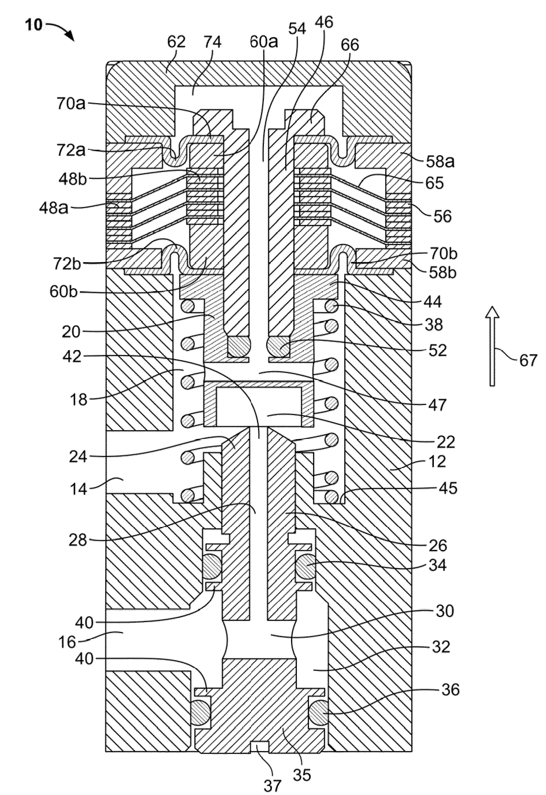
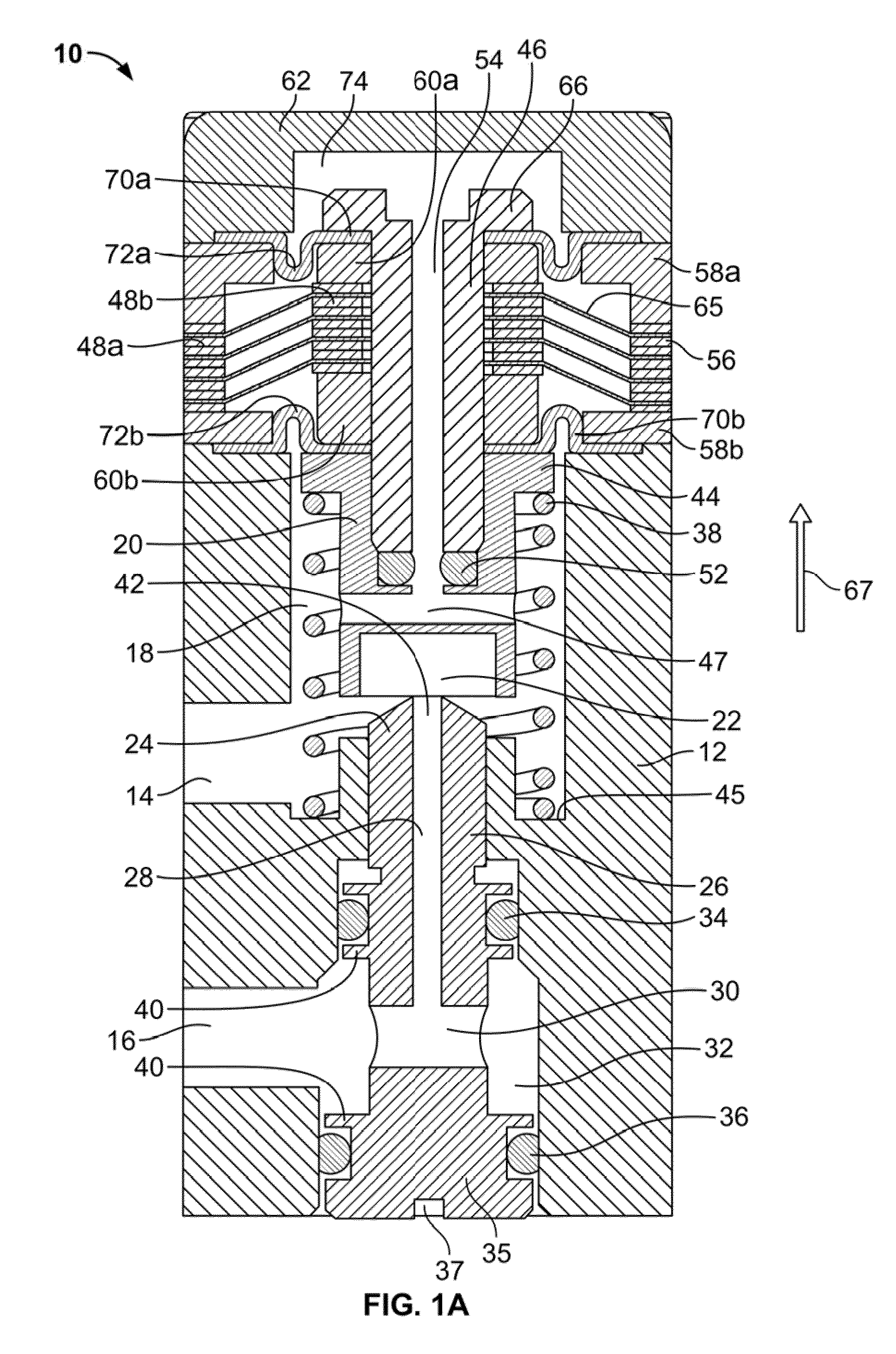
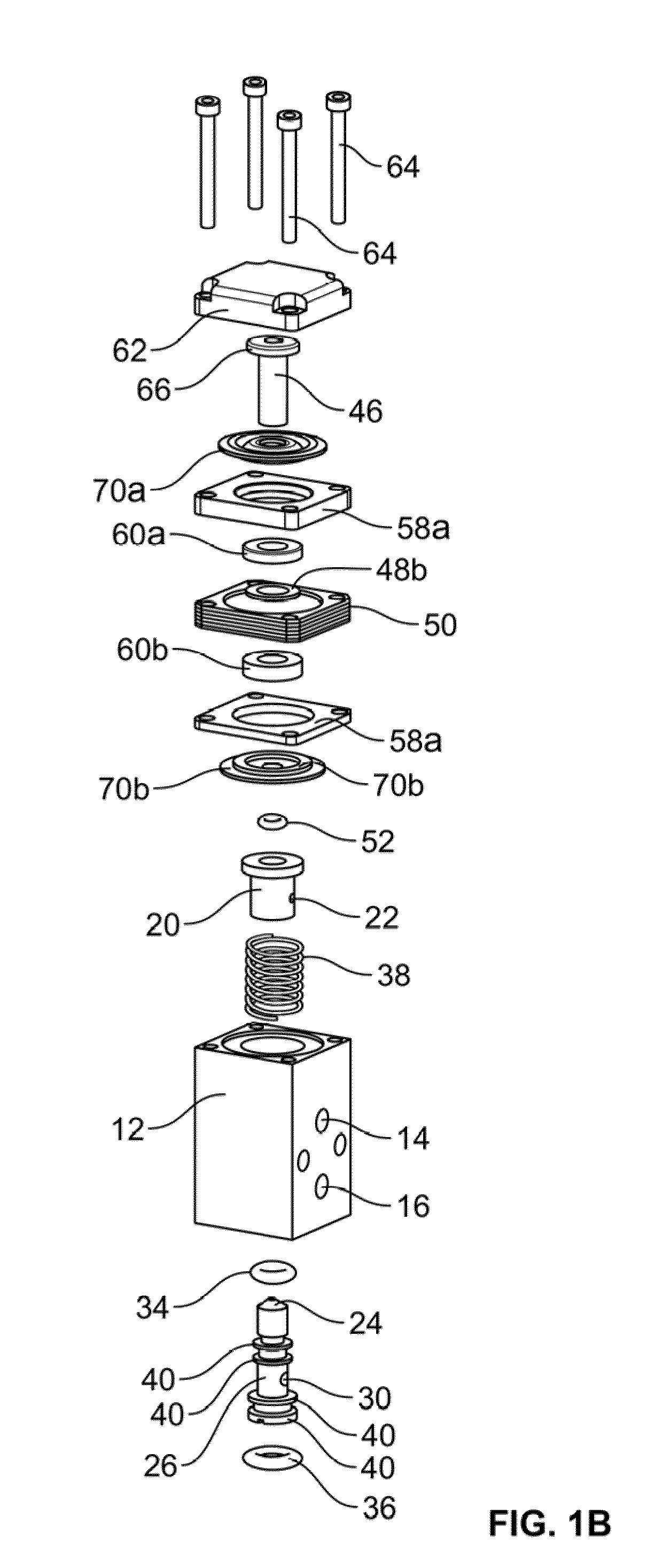
[0028]With reference to the FIGS. 1A and 1B, there is shown a fluid control system 10 of the present invention which functions as a two-way valve to allow passage of fluid from one location or chamber to another location or chamber, where the valve may be operated to allow flow in either direction through it. Fluid control system 10 includes a main housing or valve body 12 having an inlet port 14 and an outlet port 16, which may be positioned about housing 12 at any in-plane angle with respect to each other. Inlet port 14 leads to and is in fluid communication with a first or inlet chamber 18 within h...


PUM


Abstract

The present invention includes fluid control systems employing compliant electroactive materials.

Description

FIELD OF THE INVENTION[0001]The present invention relates to fluid control systems employing compliant electroactive materials. In particular, it relates to valves constructed of transducers made of compliant electroactive materials.BACKGROUND[0002]There are many types of conventional valve systems where flow through the valve is controlled by a valve actuator, such as a solenoid actuator, piezoelectric actuators, stepper actuators, etc.[0003]With solenoid-controlled valves, a plunger made of magnetic material is slidable within a solenoid coil, and a spring or other biasing means urges the plunger into contact with a valve seat or seal, or visa-versa. When no current is supplied to the solenoid, the valve is maintained closed by the spring if a normally-closed valve, and open if a normally-open valve. When current flows in the solenoid, a magnetic force acts against the spring to move the plunger, the end of which is often referred to as a poppet or orifice, away from or towards th...

Claims


Application Information

Patent Timeline
Patent Type & Authority Applications(United States)
IPC IPC(8): F01L9/04F16K31/02
CPCF01L1/352F01L2001/34426F02M51/0614F02M51/0671F16K31/02F02M63/0073F02M2200/16F02M2200/9015F02M51/0682Y10T137/87209Y10T137/86614F02M63/0015F02M63/0035F02M63/0077
Inventor ZARRABI, ALIREZAPOLYAKOV, ILYAHEIM, JONATHAN R.
Owner PARKER HANNIFIN CORP
Why Eureka
Try Eureka