Flow sensor

Active Publication Date: 2009-10-08
VYAIRE MEDICAL 203 INC
View PDF104 Cites 60 Cited by
  • Summary
  • Abstract
  • Description
  • Claims
  • Application Information

AI Technical Summary

Benefits of technology

[0023]Furthermore, the flow obstruction preferably has an aerodynamic cross sectional shape such as a diamond shape or a teardrop shape. The flow obstruction is preferably configured to promote uniform velocity across the bore at the throat section in order to improve the accuracy of

Problems solved by technology

Unfortunately, the increase in distance from the flow sensor to the endotracheal tube also increases the amount of re-breathed volume or deadspace in the patient's airway.
The increased deadspace results in re-breathing of previously exhaled gasses.
Another problem associated with flow measurement is that during the inhalation phase, inaccurate pressure measurements at the flow sensor can occur as a result of pneumatic noise in the flow.
Such pneumatic noise may include turbulence, vibrations, or asymmetric flow conditions at the ventilator end of the flow sensor (i.e., opposite the patient

Method used


Image

  • Flow sensor
  • Flow sensor
  • Flow sensor

Examples


Example

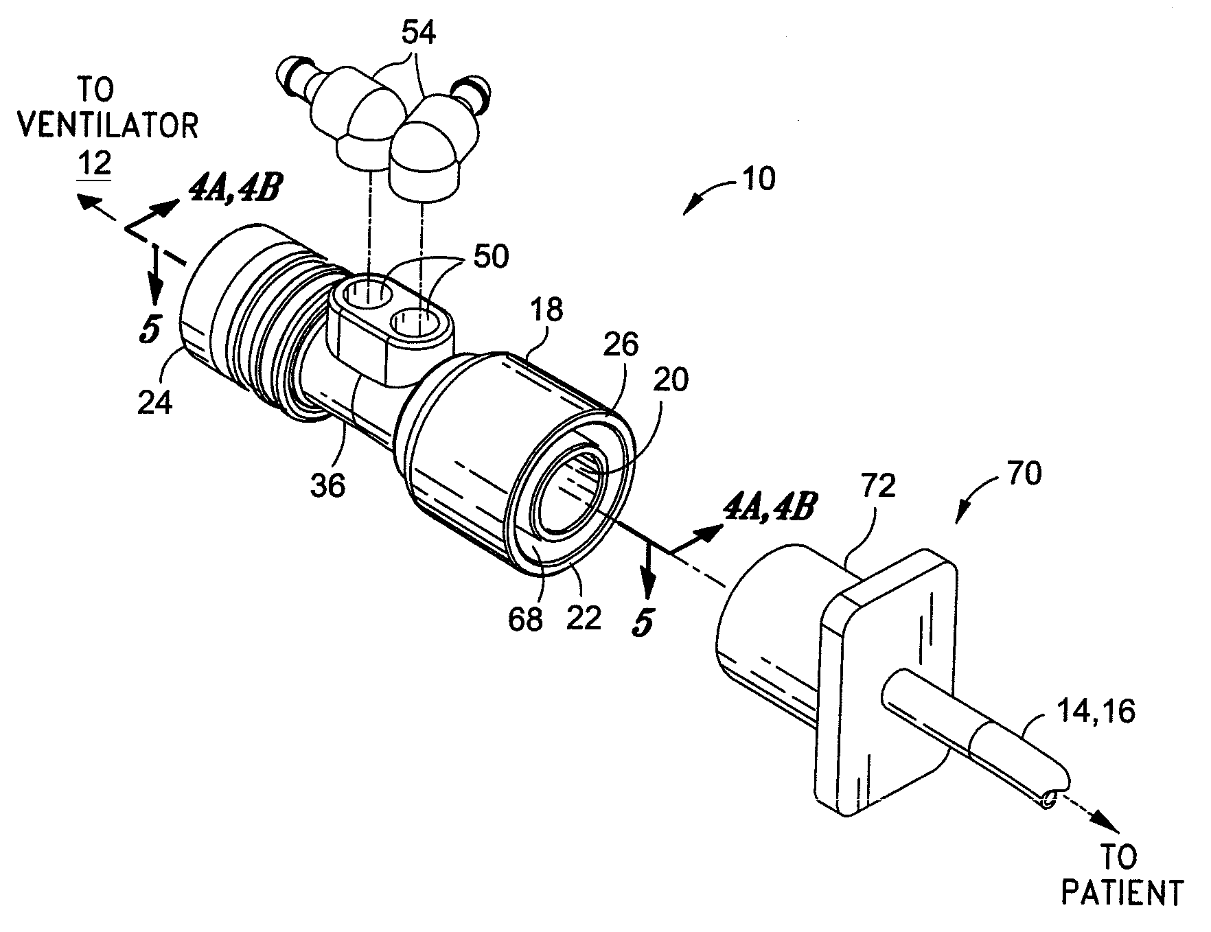
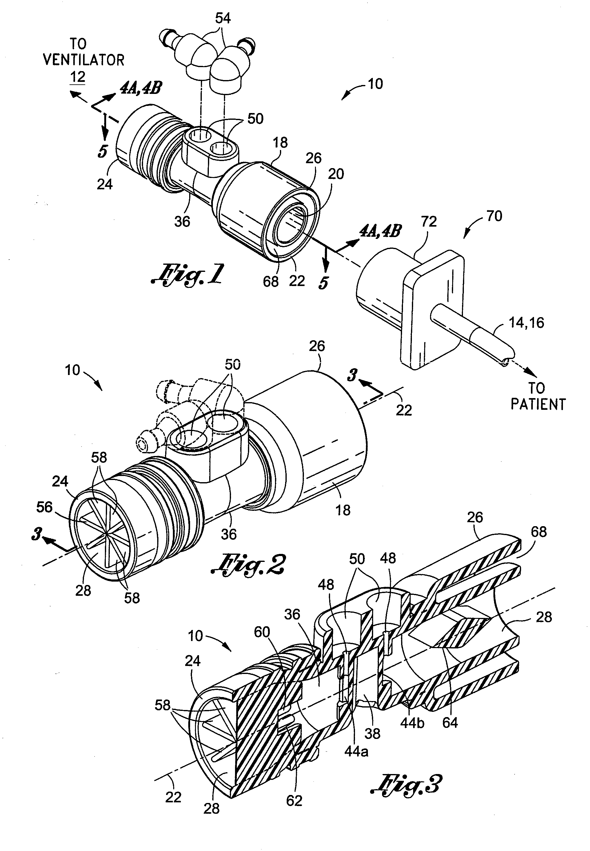
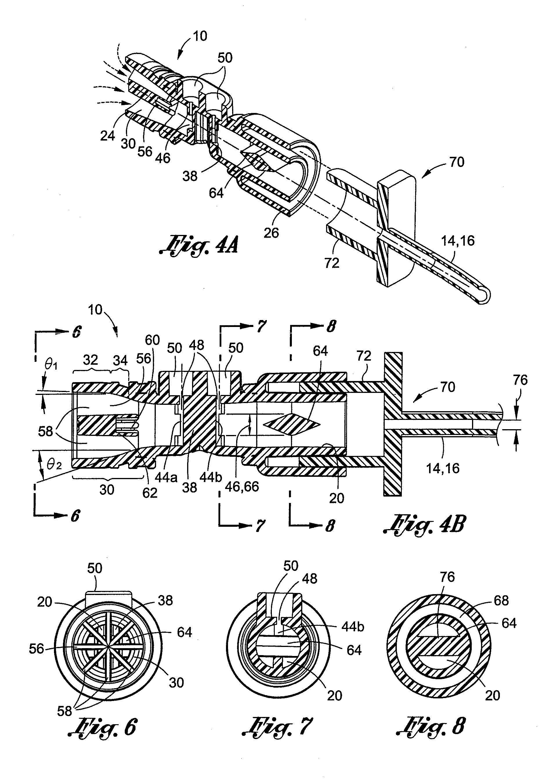
[0037]Referring now to the drawings wherein the showings are for purposes of illustrating preferred embodiments of the present invention and not for purposes of limiting the same, shown in FIGS. 1 and 2 is a perspective view of a bi-directional flow sensor 10 specifically adapted for sensing pressure within a flow passing through the flow sensor 10. The flow sensor 10 is shown as being adapted to be interconnected to a patient tube 14 such as an endotracheal tube 16 which may have a relatively small size (i.e., small inner diameter 76). The adapter 70 is frictionally engageable to the flow sensor 10 such as by insertion of the adapter 70 into an annular groove 68 formed on one end of the flow sensor 10.

[0038]The endotracheal tube 16 may also have a relatively large diameter for use with adults. Alternative configurations of the patient tube 14 may be used with the flow sensor other than endotracheal tubes. Regardless of their specific configuration, the patient tube 14 is adapted to...


PUM


Abstract

A bi-directional flow sensor is adapted for reducing pneumatic noise during pressure sensing with a flow passing through the flow sensor. The flow sensor comprises a hollow, tubular member having a throat section disposed between a ventilator end and a patient end. A flow restrictor is disposed in the throat section and is adapted to measure differential pressure in the flow. A baffle is mounted at the ventilator end and is adapted to minimize non-axial flow at pressure taps located on opposing ends of the flow restrictor. The patient end includes a flow obstruction configured to promote uniform velocity across the flow at the pressure taps during exhalation flow from the patient end to the ventilator end. The flow sensor minimizes pneumatic noise to less than 0.1 LPM to allow accurate patient flow measurement and triggering of inhalation and exhalation phases at flow rates of 0.2 LPM.

Description

CROSS-REFERENCE TO RELATED APPLICATIONS[0001]Not ApplicableSTATEMENT RE: FEDERALLY SPONSORED RESEARCH / DEVELOPMENT[0002]Not ApplicableBACKGROUND[0003]The present invention relates generally to patient ventilation systems and, more particularly, to a bi-directional flow sensor having improved accuracy in measuring respiratory flow to and from a patient.[0004]Mechanical ventilators are used to provide respiratory support to a patient by assisting in the inhalation and exhalation phases of the breathing cycle. In one arrangement, the mechanical ventilator may be connected to the patient by a wye fitting. The wye fitting is, in turn, fluidly connected to the patient's airway by a patient tube connected to a patient interface. The wye fitting may have an exhalation valve connected to one leg of the wye fitting.[0005]The exhalation valve is moved between open and closed positions according to the phase of the breathing cycle. During the inspiration phase, the exhalation valve is closed to ...

Claims


Application Information

Patent Timeline
IPC IPC(8): A61M16/00
CPCA61M16/0051A61M2016/0021A61M2016/0027A61M2016/0036A61B5/0876G01F1/36G01F1/40G01F1/50G01F15/00A61M2205/42A61M16/0866A61M16/0833A61M16/021A61B5/087A61M16/0057A61M16/04A61M16/0816
Inventor ALLUM, TODD W.WILLIAMS, MALCOM R.CIPOLLONE, JOSEPH
Owner VYAIRE MEDICAL 203 INC
Why Eureka
Try Eureka