Tank ventilation system and method for tank ventilation

a technology for ventilation systems and tanks, applied in functional valve types, condensed fuel collection/return, non-fuel substance addition to fuel, etc., to achieve reliable mechanical vacuum protection and reliable vacuum protection function

Inactive Publication Date: 2009-10-08
DR ING H C F PORSCHE AG
View PDF6 Cites 15 Cited by
  • Summary
  • Abstract
  • Description
  • Claims
  • Application Information

AI Technical Summary

Benefits of technology

[0014]The mechanical vacuum valve preferably is provided in the vapor chamber of the tank and is spatially separate from the electrically activatable check valve. It is possible to select a suitable range for this purpose. A reliable vacuum protection function is ensured by means of the structurally very simple solution.
[0015]The preferred placement of a vacuum protection valve in the vapor chamber of the tank may not be possible due to installation space...

Problems solved by technology

However, the mechanical vacuum valve specifically is not arranged in the con...

Method used


Image

  • Tank ventilation system and method for tank ventilation
  • Tank ventilation system and method for tank ventilation

Examples


Embodiment Construction

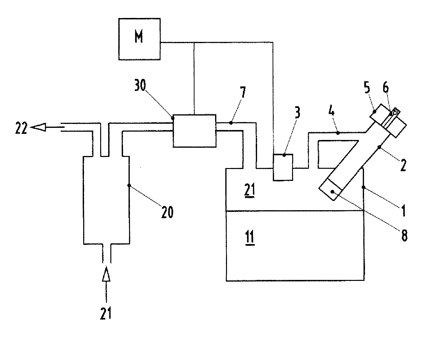
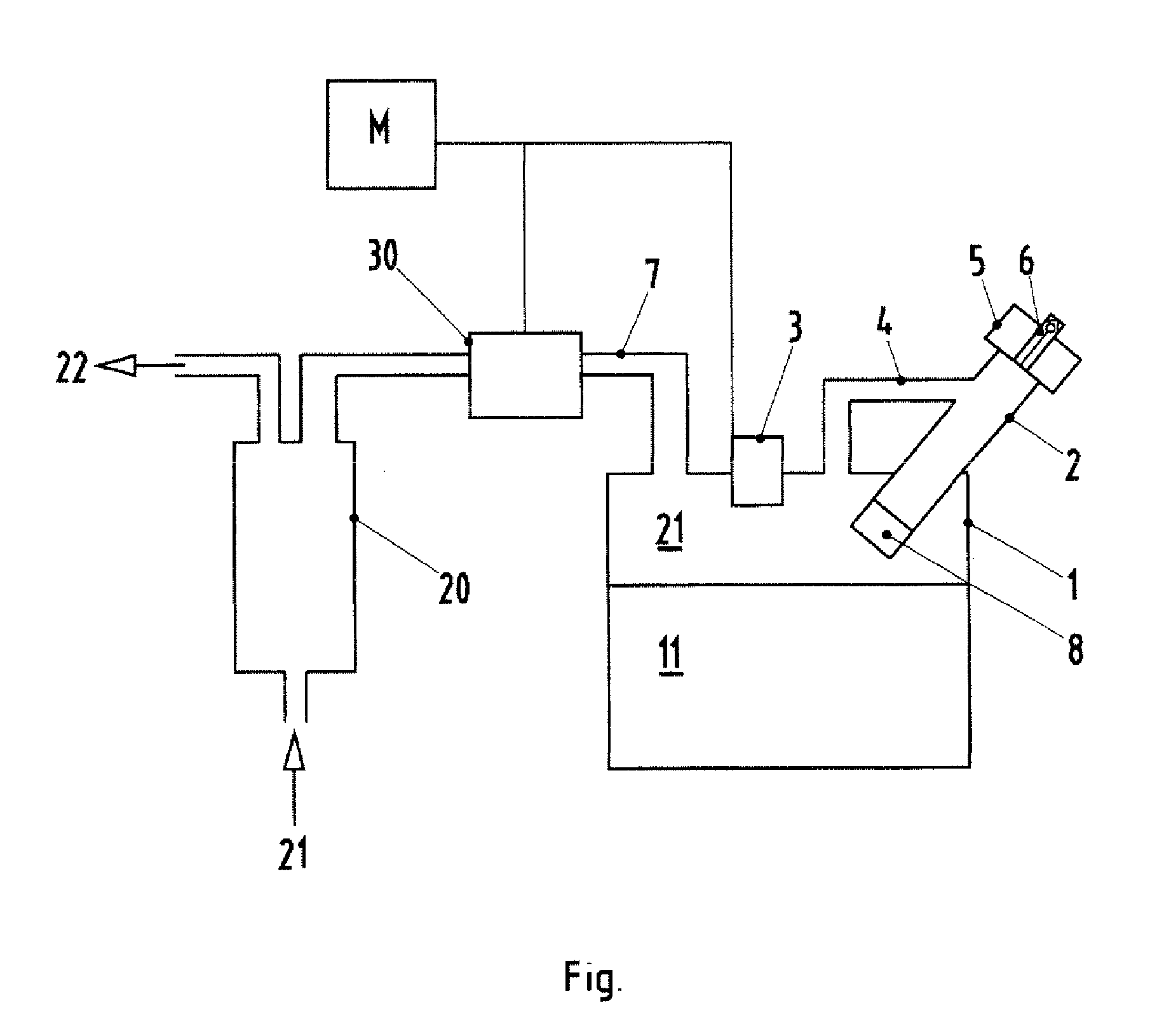
[0018]The FIGURE illustrates a tank ventilation system for a tank 1. The tank 1 can be filled with fuel 11 via a filler neck 2. A vapor chamber 12 is situated above the fuel 11 and defines that region of the tank 1 that is not filled with fuel 11. A tank cover 5 is provided to close off the filler neck 2. More particularly, the tank cover 5 is removed to open the filler neck 2 and the fuel 11 then is filled into the tank 1 through the filler neck 2. A differential pressure sensor 3 is provided for measuring the tank internal pressure as a pressure difference between the vapor chamber 12 of the tank and the environment. An activated carbon filter 20 is provided to adsorb the fuel vapors 21. The activated carbon filter 20 is connected to the vapor chamber 12 of the tank 1 via a connecting line 7. The connecting line 7 has an electrically activatable check valve 30. The check valve 30 normally is closed, and no fuel vapor can pass from the tank 1 into the activated carbon filter 20 whe...


PUM


Abstract

A tank ventilation system for a motor vehicle includes a tank (1) for combustible fuels. An activated carbon filter (20) is connected to the tank (1) via a connecting line (7) and adsorbs hydrocarbon vapors of the tank (1) for deaeration. An electrically activatable check valve (30) is in the connecting line. A differential pressure sensor (3) measures the pressure difference between the vapor chamber (21) of the tank (1) and the environment. The connecting line is formed without a vacuum valve. A mechanical vacuum valve (6) is provided for tank aeration with respect to the environment. The check valve is closed if the pressure difference measured by the differential pressure sensor is below a fixed, positive threshold value, and is open if the pressure difference is above the threshold value.

Description

CROSS-REFERENCE TO RELATED APPLICATIONS[0001]This application claims priority under 35 USC 119 to German Patent Application No. 10 2008 017004.6 filed on Apr. 3, 2008, the entire disclosure of which is incorporated herein by reference.BACKGROUND OF THE INVENTION[0002]1. Field of the Invention[0003]The invention relates to a tank ventilation system and to a method for tank ventilation.[0004]2. Description of the Related Art[0005]Motor vehicles conventionally have an activated carbon filter between the environment and the tank that supplies the internal combustion engine with combustible fuel. The activated carbon filter functions as a buffer for fuel vapors from the vapor chamber of the tank, and specifically from those regions of the tank that are not filled with fuel. The activated carbon filter is regenerated or purged on demand with a fresh air flow that is conducted over the hydrocarbon-laden carbon particles. The fresh air flow absorbs the hydrocarbons and transports the hydroc...

Claims


Application Information

Patent Timeline
IPC IPC(8): F16K21/04
CPCB60K15/035F02M25/089F02M25/08Y10T137/7837
Inventor MENKE, ANDREAS
Owner DR ING H C F PORSCHE AG
Why Eureka
Try Eureka