Structure and paint for forming surface coat layer

a technology of surface coating and structure, which is applied in the direction of machines/engines, traffic signals, roads, etc., can solve the problems of difficult to completely prevent the discharge of toxic substances at the start of the engine, the failure of catalysts to provide their functions, etc., and achieve the effect of low heat conductivity

Active Publication Date: 2015-04-16
IBIDEN CO LTD
View PDF2 Cites 0 Cited by
  • Summary
  • Abstract
  • Description
  • Claims
  • Application Information

AI Technical Summary

Benefits of technology

[0065]If the low melting glass containing any of the above materials is used as the amorphous inorganic material in the paint of the embodiment of the present invention,

Problems solved by technology

In a conventional exhaust gas purifying system, the temperature of the catalytic converter at the start of the engine is lower than the catalyst activation temperature, an

Method used


Image

  • Structure and paint for forming surface coat layer
  • Structure and paint for forming surface coat layer
  • Structure and paint for forming surface coat layer

Examples


example 1

(1) Preparation of Base Material

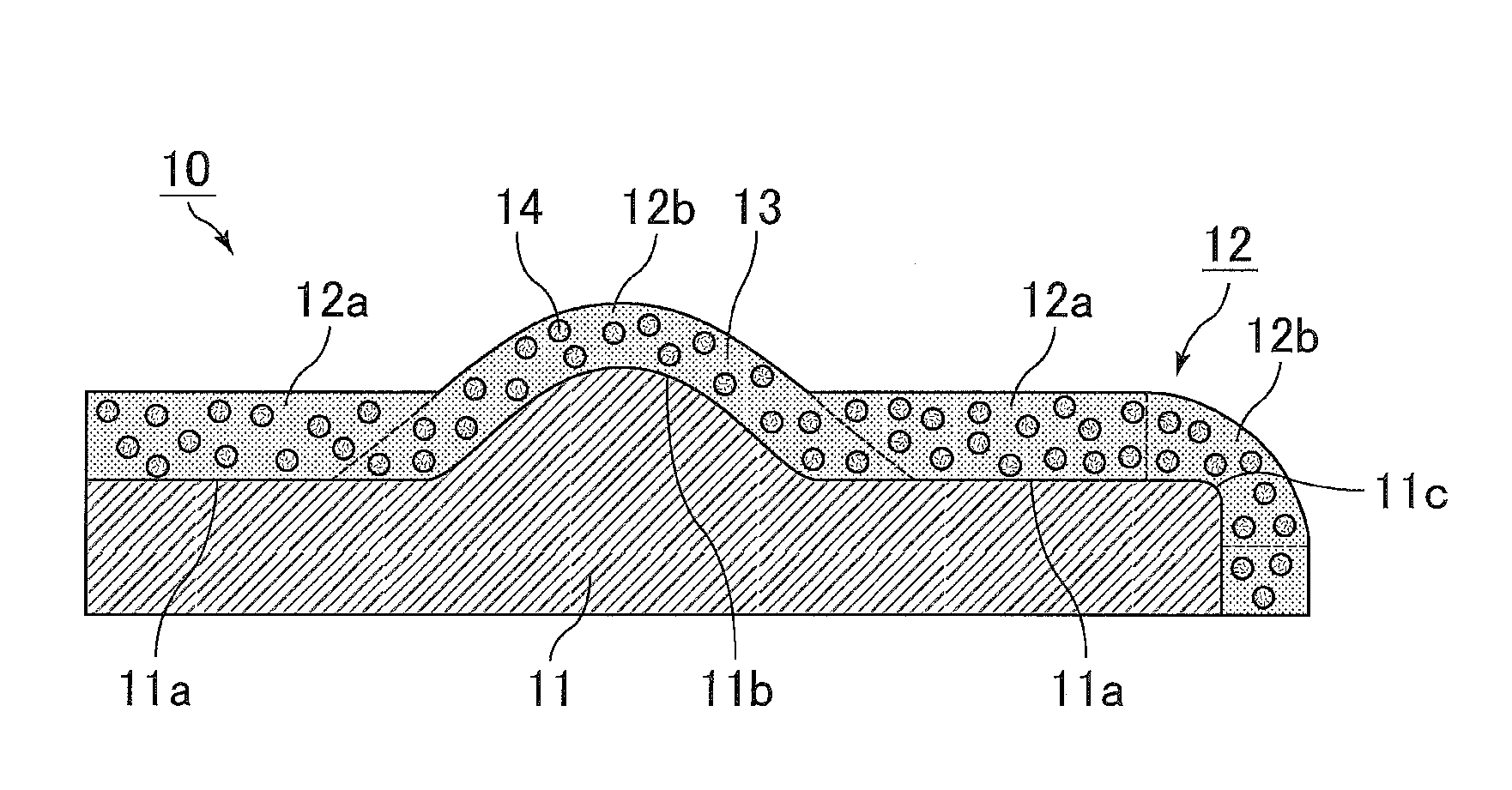
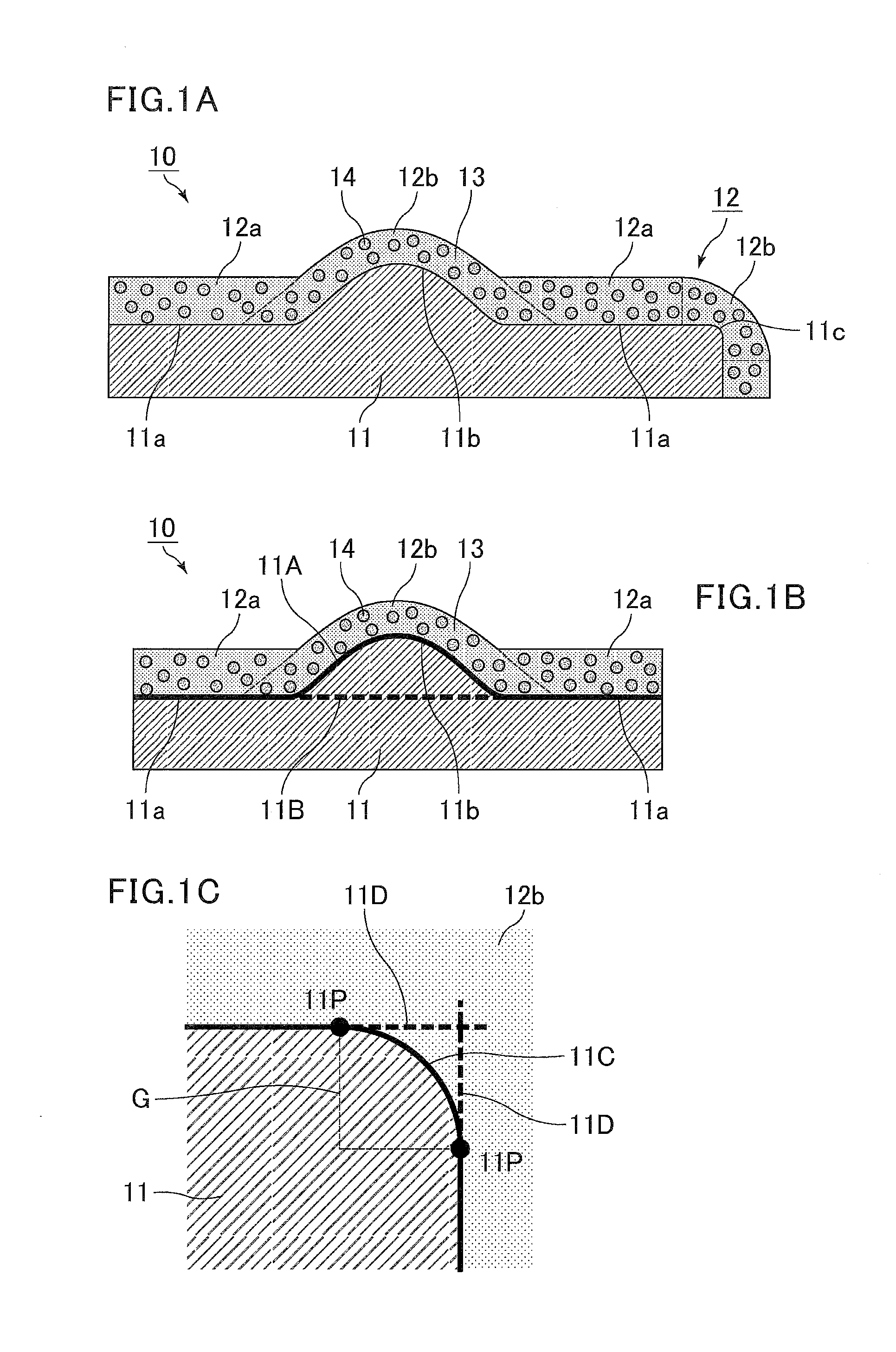
[0182]A plate-shaped stainless steel base material (made of SUS430) having a size of 40 mm (length)×40 mm (width)×1.5 mm (thickness) including a semicylindrical weld bead having a height of 5 mm, a width of 10 mm, and a length of 40 mm was prepared as a metal base which is the application target. This metal base was subjected to ultrasonic washing in an alcohol solvent, and subsequently subjected to a sandblast treatment so that the surface (on both sides) of the metal base was roughened. The sandblast treatment was carried out using Al2O3 abrasive grains of #100 for 10 minutes.

[0183]With a surface-roughness measuring machine (HANDY SURF E-35B from Tokyo Seimitsu Co., Ltd.), the surface roughness of the metal base was determined with a measurement interval of 10 mm. The results showed that the surface roughness RzJIS of the metal base material was 8.8 μm.

[0184]A plate-like base was produced by the above treatments.

(2) Preparation of Paint for Forming ...

examples 2 to 8

[0198]A surface coat layer was formed in substantially the same manner as in Example 1, except that the kind of the base as the application target, the kind, average particle size, and percentage by weight of the crystalline inorganic material used to produce the paint for forming a surface coat layer, and the concentration of the amorphous inorganic material were changed as shown in Table 1. The application target, properties of the paint for forming a surface coat layer (the kind of the crystalline inorganic material, the average particle size of the crystalline inorganic material, the percentage by weight of the crystalline inorganic material, the concentration of the amorphous inorganic material), and the properties of the overcoat layer (the kind of crystalline inorganic material, the average particle size of the crystalline inorganic material, the percentage by weight of the crystalline inorganic material, the concentration of the amorphous inorganic material) are shown in Tab...


PUM

PropertyMeasurementUnit
Lengthaaaaaaaaaa
Percent by massaaaaaaaaaa

Abstract

A structure includes a surface coat layer of which the thickness on a bump such as a weld bead and a weld spatter or an edge portion, possibly formed on the surface of a base, is not greatly different from the thickness on a flat portion. The structure therefore has excellent properties including heat insulation properties and electrical insulation properties. The structure includes a base that is made of a metal, and has a flat portion and at least one of a bump and an edge portion on a surface; and a surface coat layer that is formed from an amorphous inorganic material and particles of a crystalline inorganic material, and covers the surface of the base, the surface coat layer including a first coat portion covering the flat portion and a second coat portion covering the at least one of a bump and an edge portion.

Description

CROSS-REFERENCE TO RELATED APPLICATIONS[0001]The present application claims priority under 35 U.S.C. §119 to Japanese Patent Application No. 2013-213254, filed Oct. 10, 2013. The contents of this application are incorporated herein by reference in their entirety.BACKGROUND OF THE INVENTION[0002]1. Field of the Invention[0003]The present invention relates to a structure and a paint for forming a surface coat layer.[0004]2. Discussion of the Background[0005]A catalytic converter is provided in the path of an exhaust pipe to treat toxic substances contained in exhaust gas discharged from an engine.[0006]It is necessary to maintain the temperatures of exhaust gas, an exhaust pipe through which the exhaust gas passes, and the like at temperatures suitable for catalytic activation (hereinafter, also referred to as catalyst activation temperatures) in order to improve conversion efficiency of toxic substances by a catalytic converter.[0007]In a conventional exhaust gas purifying system, th...

Claims


Application Information

Patent Timeline
IPC IPC(8): C09D101/28C08K3/38C08K3/22
CPCC09D101/28C08K3/22C08K3/38C08K2003/2227C03C8/14C03C8/20C23D5/00F01N13/102F01N13/14F01N13/16C03C2207/04C03C2207/06F01N2510/02C23D5/005F01N13/08Y10T428/24372Y10T428/24612
Inventor MUTSUDA, FUMIYUKIFUJITA, YOSHITAKA
Owner IBIDEN CO LTD
Why Eureka
Try Eureka