Combustion-engined setting tool

a technology of combustion engine and setting tool, which is applied in the direction of positive displacement liquid engine, metal working apparatus, piston pump, etc., can solve the problems of reducing the available setting energy, interfering with the function of setting tool, and loose particles of elastomeric springs, etc., and achieves high setting frequency

Inactive Publication Date: 2009-10-08
HILTI AG
View PDF14 Cites 26 Cited by
  • Summary
  • Abstract
  • Description
  • Claims
  • Application Information

AI Technical Summary

Benefits of technology

[0011]Advantageously, the pump is formed as an electrical suction pump for producing a suction air flow and is connected with the combustion chamber. The pump produces underpressure in the combustion chamber, so that environmental pressure, which acts on a side of the drive piston remote from the combustion chamber, can return the drive piston to its initial position.
[0012]It is further advantageous when there is provided a control unit for controlling the pump based on data produced by sensors. This insures an efficient operation of the pump and energy saving.
[0014]It is further advantageous when the sensors includes a temperature sensor, so that the control unit actuates the pump only when the temperature difference between the tool temperature or the combustion chamber temperature and the environmental temperature is below a certain value. This insures a complete return of the drive piston in its initial position. This also permits to achieve a high energy efficiency of the piston returning device.
[0015]It is also advantageous when an electrically controlled check valve is provided between the pump and the combustion chamber and which is controlled by the controlled unit. The check valve is closed by the control unit when the drive piston is returned in its initial position. This insures that pressure waves, which are produced in the combustion chamber during a setting process, do not reach the pump and damage it. Further, at the end of a setting process which is detected, e.g., by the piston sensor or is determined by time-control-means, the control unit can open the check valve, connecting the pump and the combustion chamber. Thereby, gases are aspirated from the combustion chamber, producing vacuum therein.

Problems solved by technology

The drawback of the setting tool disclosed in the German publication consists in that the drive piston at a certain state of wear does not return completely in its initial position, which leads to reduction of the available setting energy.
On the other hand, particles of the elastomeric spring can become loose, interfering with the setting tool functions.
The drawback of the tool disclosed in the European Publication consists in that a faulty position of the piston can occur when, e.g., the friction of the drive piston increases as a result of contamination, and the piston does not return completely in its initial position, or when as a result of a too small difference between the environmental temperature and the power tool temperature, the pressure difference is not sufficient for a complete return of the drive piston in its initial position.

Method used


Image

  • Combustion-engined setting tool
  • Combustion-engined setting tool

Examples


Embodiment Construction

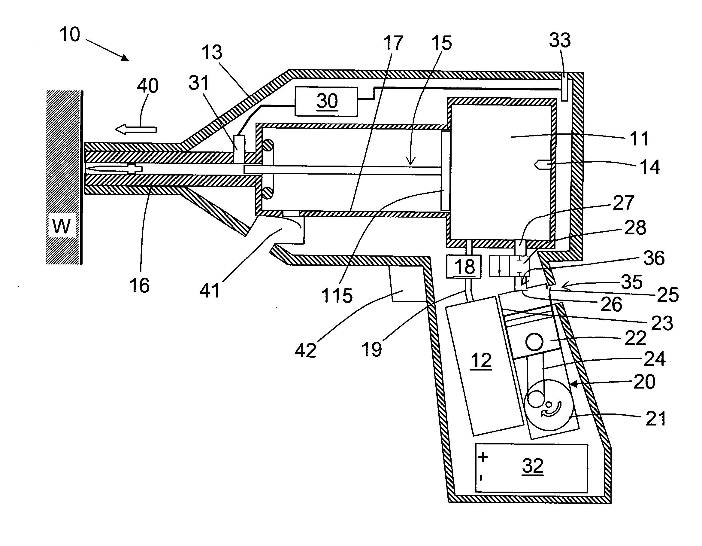
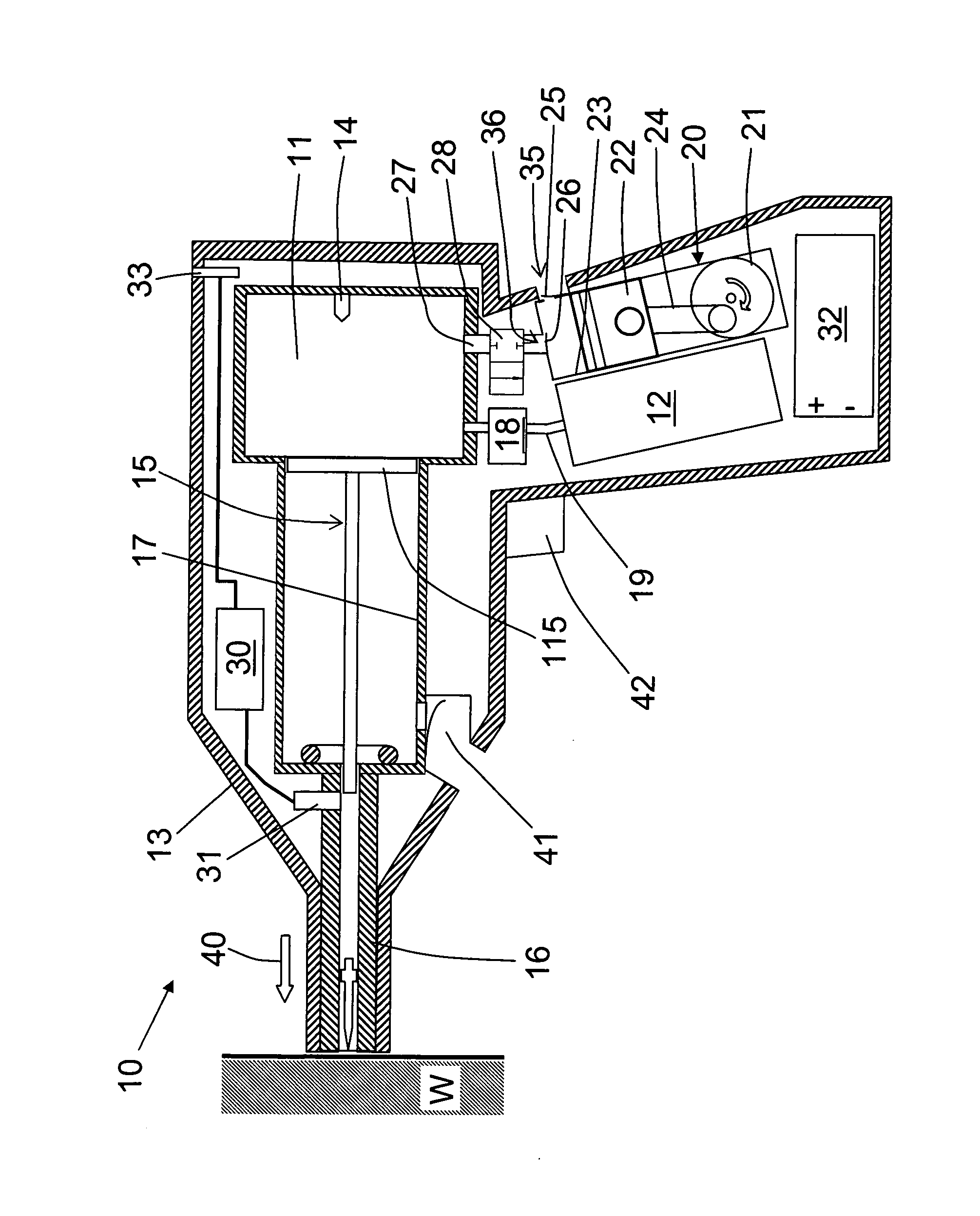
[0019]A setting tool 10 according to the present invention, which is shown in the drawing, can be operated with a fuel gas or an evaporated liquid fuel and includes a housing 13 and a setting mechanism located in the housing. The setting mechanism drives a fastening element such as nail, bolt, etc. in a workpiece W when the setting tool 10 is pressed with its bolt guide 16 against the workpiece and is actuated. For actuation of the setting tool 10, there is provided, in addition to a safety switch in form of a contact switch, a trigger switch 42. The trigger switch 42 is located on a handle of the setting tool 10.

[0020]The setting mechanism includes, among others, a combustion chamber 11, a piston guide 17 in which a drive piston 15 is displaceably supported, and the bolt guide 16 in which a fastening element can be displaced. The fastening element can be driven in a workpiece with a forward-movable, setting direction-side, end of the drive piston 15. The bolt guide 16 adjoins, in t...


PUM


Abstract

A combustion-engined setting tool (10) for driving fastening elements in a workpiece includes a combustion chamber (11), a drive piston (15) displaceable in a piston guide (17) and driven by expanding gases produced in the combustion chamber (11), and a device for returning the drive piston (15) in its initial position as a result of pressure difference between chambers formed on opposite axial sides of the piston head (115), and including a pump (20).

Description

BACKGROUND OF THE INVENTION[0001]1. Field of the Invention[0002]The present invention relates to a combustion-engined setting tool for driving fastening elements in a workpiece and including a combustion chamber for fuel, a piston guide, a drive piston displaceable in the piston guide, having a piston head and driven by expanding gases produced in the combustion chamber, and a device for returning the drive piston in its initial position as a result of pressure difference between chambers formed on opposite axial sides of the piston head.[0003]2. Description of the Prior Art[0004]Setting tools of the types described above can operate on gaseous or evaporated liquid fuels which are combusted in a combustion chamber and thereby drive a drive piston for driving fastening elements. After completion of a setting process, the drive piston should be returned to its initial position adjacent to the combustion chamber, so that the setting tool is ready for a next setting process.[0005]German...

Claims


Application Information

Patent Timeline
Patent Type & Authority Applications(United States)
IPC IPC(8): B25C1/14F04B35/04
CPCB25C1/08
Inventor HAHN, CHRISTIANERHARDT, ROLF
Owner HILTI AG
Why Eureka
Try Eureka