Utility Tray Module for Power Plant Construction

a power plant and utility tray technology, applied in the field of utility tray, can solve the problems of long power plant construction duration, complex layout of utility tray within electricity power generation plant, and requiring extensive engineering resources, and achieve the effects of saving laboring hours and expense, convenient assembly, and quick installation into complex layou

Inactive Publication Date: 2009-10-08
CHOU SHUI FANG
View PDF3 Cites 6 Cited by
  • Summary
  • Abstract
  • Description
  • Claims
  • Application Information

AI Technical Summary

Benefits of technology

[0006]The present invention is drawn to a utility tray for accommodating cables, light sources, pipelines, ventilation ducts, and other utilities. It comprises a plurality of tray modules that can be locked into the existing structural component of concrete and be assembled laterally and vertically to desired length and high. Accordingly, several objects and advantage to the present invention are: (1) to provide a utility tray that can be self anchored to concrete structural component(s); (2) to provide a utility tray which can serves as concrete mold used for concrete pouring; (3) to provide a utility tray that is easily assembled and quickly install into complex layout, thus saves laboring hours and expense; (4) to provide a utility tray that matches high standard of seismic qualification; (5) to provide a utility tray that can facilitate the installation of fire protection insulation. Still further objects and advantages of present invention will become apparent from a consideration of the drawings and ensuing description.

Problems solved by technology

The complexity of utility tray layout within electricity power generation plant commonly demands extensive laboring hours.
The seismic qualification of such utility tray system for nuclear power plant also demands extensive engineering resources.
Conventionally, the construction of the utility tray system is commonly scheduled after the construction of the building structure, which results in lengthy power plant construction duration.
This cable separation requirement has made the layout of the utility tray become further complex.
Additionally, the extra labor on installing added-on fire protection insulation will lengthen the construction time.

Method used


Image

  • Utility Tray Module for Power Plant Construction
  • Utility Tray Module for Power Plant Construction
  • Utility Tray Module for Power Plant Construction

Examples


Embodiment Construction

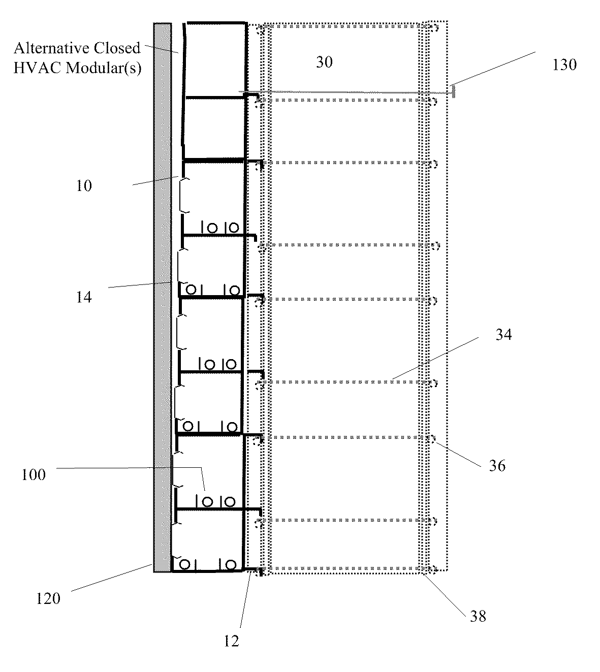
[0039]The present invention is drawn to a utility tray for accommodating cables, light sources, pipelines, ventilation ducts, and other utilities. It comprises a plurality of tray modules that can be locked into the existing structural component of concrete and be assembled laterally and vertically to desired length and high.

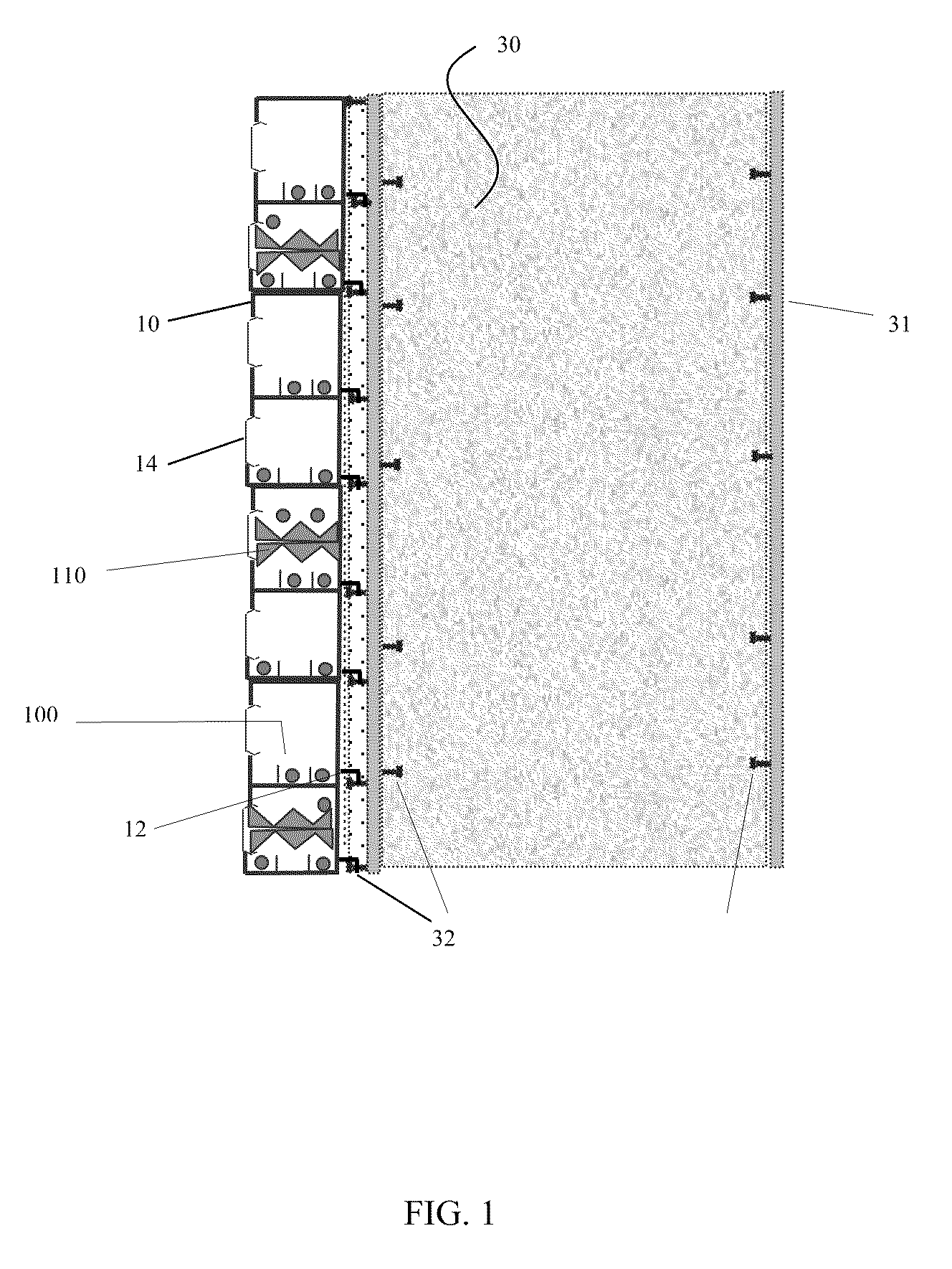
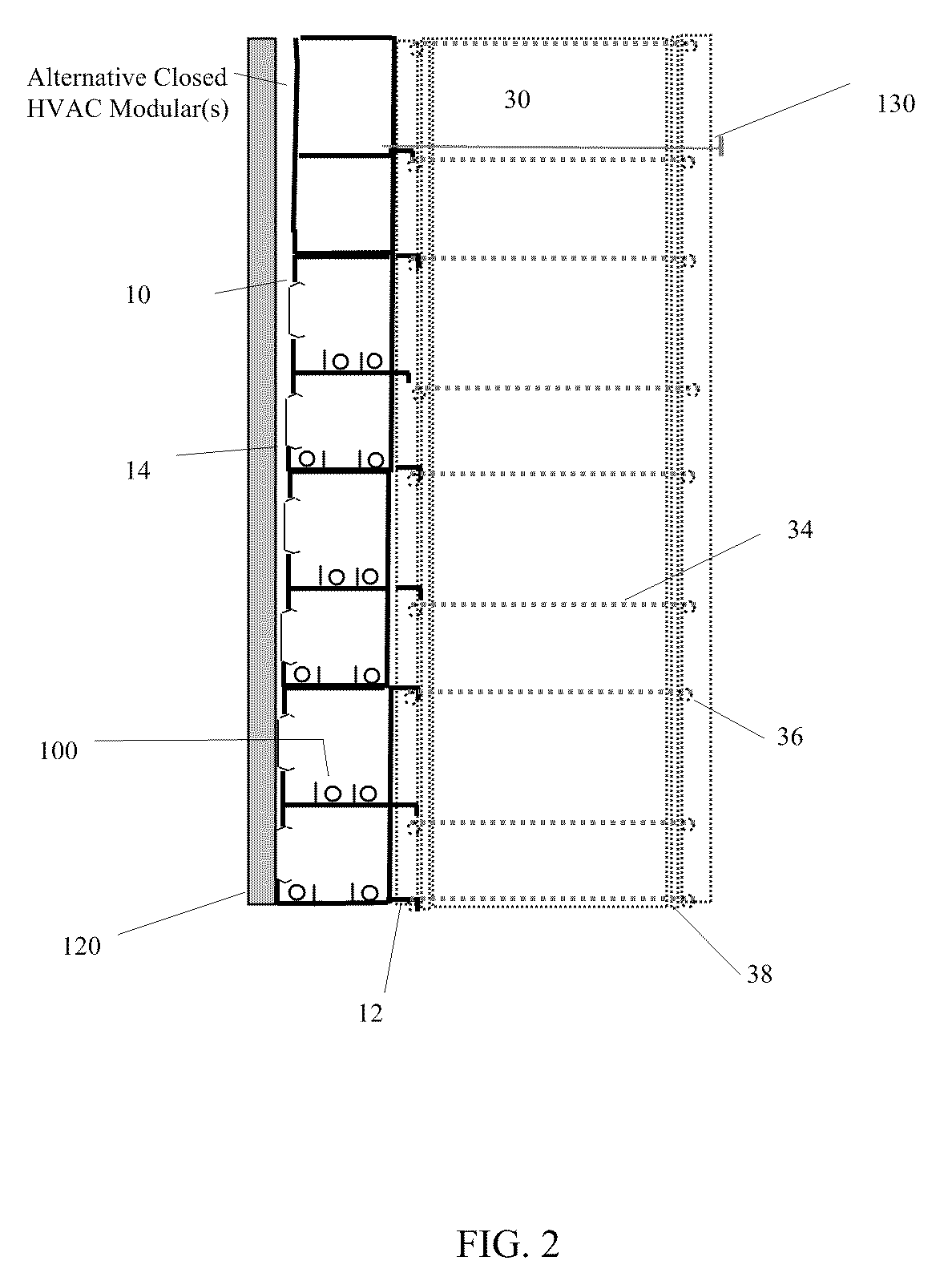
[0040]FIG. 1 is a side view of one embodiment of the present invention. A utility tray comprises a plurality of tray modules 10 (detailed see FIGS. 4 & 5). Each tray module 10 has a hanging strip 12 that firmly hangs to the welded studs 32 or welded channel segment(s) on steel-reinforcing plates when these steel plates31 are used as a mold for concrete pouring. FIG. 1 shows eight tray modules 10 that assemble vertically and stack together. Certainly, these tray modules 10 can be assembled vertically to any desired height and / or laterally to any desired length. Besides welded studs 32, the hanging strips 12 can attach to the welded channels or fastener on the ste...


PUM

PropertyMeasurementUnit
lengthaaaaaaaaaa
heightaaaaaaaaaa
timeaaaaaaaaaa

Abstract

Utility tray for accommodating cables, pipelines, and other utilities comprises a plurality of tray modules. The tray module has a hanging strip that attaches to the structural component of the concrete, such as welded studs and rebars. Concrete locking groove is provided to interlock the concrete wall, thus rigidity of attachment to the concrete is enhanced. A vertical locking protrusion and a vertical locking groove are provided to position and interlock tray modules vertically. A lateral locking fin and a offset notch are provided to interlock tray modules laterally. Tray modules can be made by extrusion method and roll-formed method. The tray modules are assembled laterally and vertically to form a utility tray of desired length and height. Besides accommodating utilities, the utility tray can serve as the construction mold during concrete pouring.

Description

CROSS-REFERENCE TO RELATED APPLICATIONS[0001]This application claims the benefit of U.S. Provisional Application Ser. No. 61 / 042,783 filed on Apr. 7, 2008.BACKGROUND OF THE INVENTION[0002](1) Field of Invention[0003]This invention relates to a utility tray that accommodates cables, light sources, pipelines, ventilation ducts, and other utilities; specially relates to a utility tray that can be integrated and direct locked into the existing structural components of concrete walls, particularly locked into the existing concrete structures of power plant construction.[0004](2) Description of Related Art[0005]The complexity of utility tray layout within electricity power generation plant commonly demands extensive laboring hours. The seismic qualification of such utility tray system for nuclear power plant also demands extensive engineering resources. Conventionally, the construction of the utility tray system is commonly scheduled after the construction of the building structure, which...

Claims


Application Information

Patent Timeline
Patent Type & Authority Applications(United States)
IPC IPC(8): F16L3/00E04C2/52B21K23/00
CPCF16L3/26Y10T29/49623H02G3/0431
Inventor CHOU, SHUI-FANG
Owner CHOU SHUI FANG
Why Eureka
Try Eureka