
Sample stage apparatus and method of controlling the same

Inactive Publication Date: 2009-10-08
HITACHI HIGH-TECH CORP
View PDF2 Cites 13 Cited by
  • Summary
  • Abstract
  • Description
  • Claims
  • Application Information

AI Technical Summary

Benefits of technology

[0010]An object of the present invention is to provide a stage apparatus capable of reducing a waste time for positioning, which occurs when a positional deviation increase, and performing high-accuracy positioning.
[0012]According to the present invention, it is possible to reduce a waste time for positioning, which occurs when a positional deviation increases, and perform high-accuracy positioning.

Problems solved by technology

(1) In the case of a stage apparatus including a plurality of tables with different axes, although the positioning of one of the tables is completed, the positioning of the other table is not completed yet, which results in a waste time for positioning.
The waste time for positioning and the positional deviation may further increase due to an increase in the speed of the table and an increase in inertia as growing the size of the table.

Method used


Image

  • Sample stage apparatus and method of controlling the same
  • Sample stage apparatus and method of controlling the same
  • Sample stage apparatus and method of controlling the same

Examples


Embodiment Construction

[0019]Hereinafter, a positioning control technique of a sample stage apparatus according to the present invention will be described in detail with reference to the accompanying drawings.

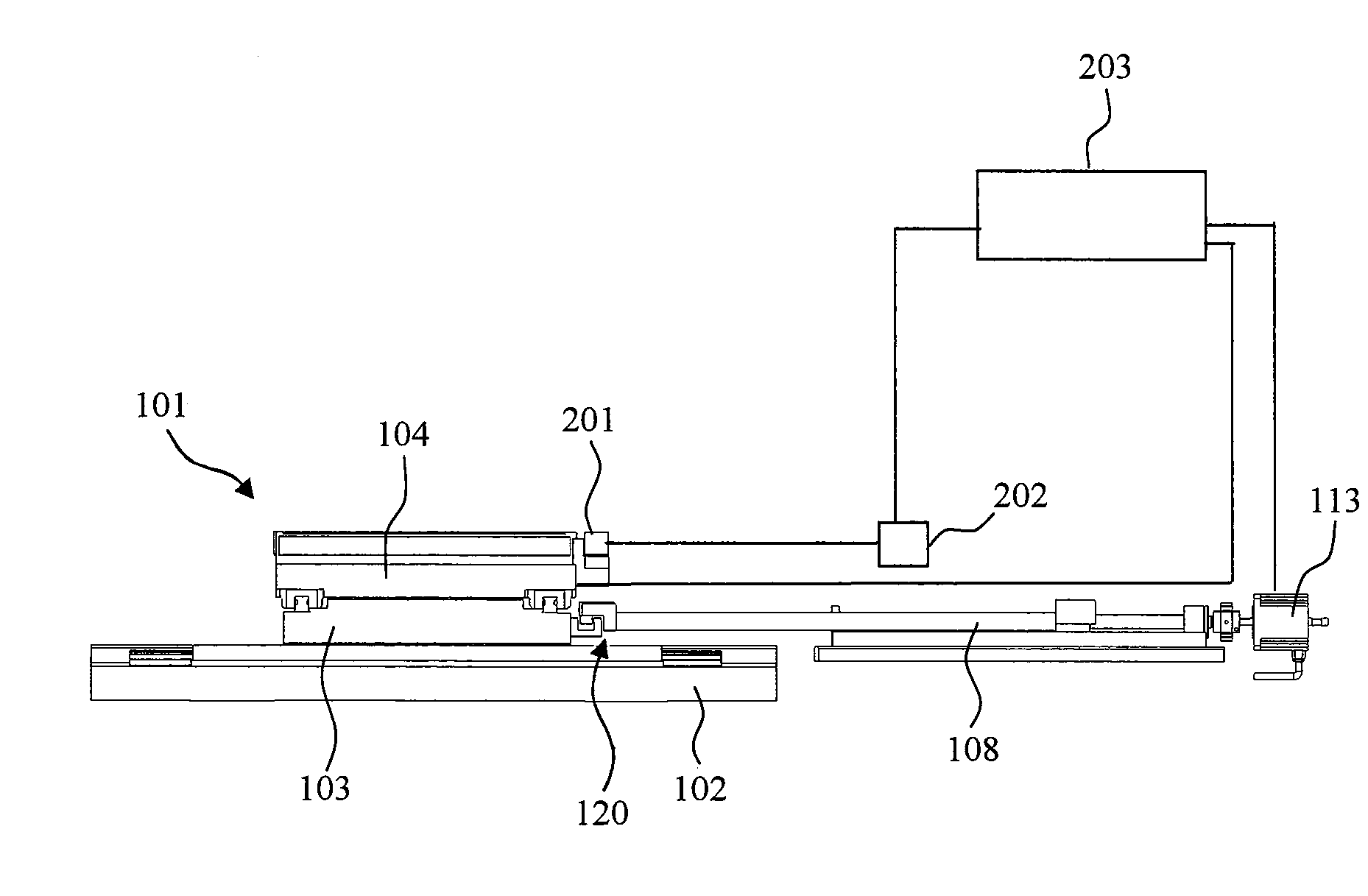
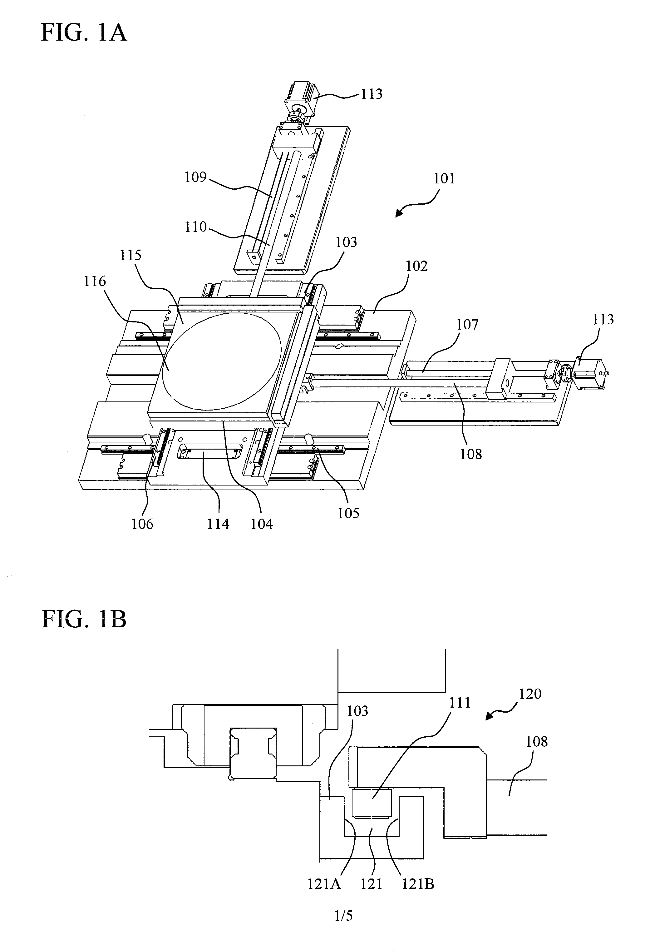
[0020]FIG. 1A is a diagram illustrating an example of the sample stage apparatus according to the present invention. A sample stage apparatus 101 includes X and Y tables that are driven by stepping motors. The sample stage apparatus 101 includes a base 102, an X table 103, and a Y table 104. The X table 103 can be moved in an X direction by an X-direction guide mechanism 105, and the Y table 104 can be moved in a Y direction by a Y-direction guide mechanism 106. The X table 103 and the Y table 104 are independently moved.

[0021]A driving mechanism of the X table 103 includes an X ball screw 107, an X rod 108, and a stepping motor 113. When the X ball screw 107 is rotated by the stepping motor 113, the X rod 108 is moved in a straight line to press the X table 103 in the X direction. Similarly, a drivi...


PUM


Abstract

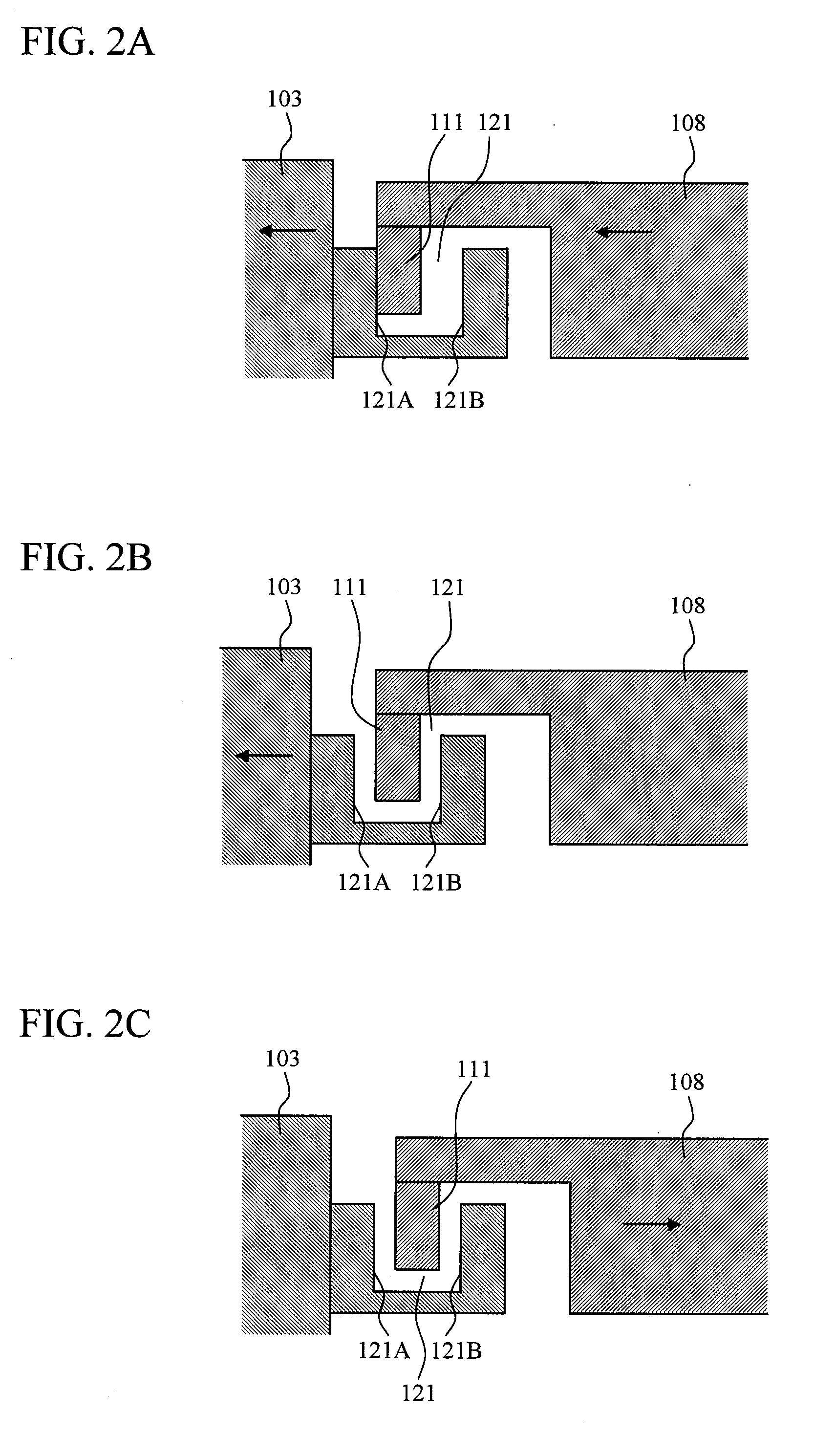
The present invention provides a stage apparatus capable of reducing a positioning time without increasing a positional deviation. A positioning control method of a sample stage apparatus includes: a high-speed movement step of moving a table to a high-speed movement target position at a first movement speed; a positional deviation correcting step of moving the table to a low-speed positioning step start position at a second movement speed that is lower than the first movement speed; a low-speed positioning step of moving the table to a target position at a third movement speed that is lower than the second movement speed. After the low-speed positioning step is completed, a rod connected to a motor returns to its original position to separate a pin of the rod side from a concave portion of the table side.

Description

BACKGROUND OF THE INVENTION[0001]1. Field of the Invention[0002]The present invention relates to a sample stage that holds a sample, and more particularly, to a positioning technique of a sample stage apparatus including X and Y tables.[0003]2. Description of the Related Art[0004]Precision machines and test apparatuses use sample stages that hold samples. The sample stage requires high-speed movement and high-accuracy positioning. An example of an apparatus using the sample stage is an electron microscope.[0005]Japanese Patent Application Laid-Open (JP-A) No. 2007-80660 (corresponding to U.S. Pat. No. 7,435,974) discloses a stage that has a driving mechanism including a stepping motor and a feed screw and performs open-loop control to achieve high-speed and high-accuracy positioning. In the driving mechanism, a gap is provided in a connection portion between a table of the stage and the feed screw in order to prevent the movement of the stage due to the thermal expansion of the feed...

Claims


Application Information

Patent Timeline
IPC IPC(8): G05B11/18
CPCH01J37/20H01J2237/20292H01J2237/20285H01J2237/20228
Inventor FUJITA, MASASHINAKAGAWA, SHUICHIKOBAYASHI, TAKASHI
Owner HITACHI HIGH-TECH CORP
Learn More