Fuel gas direct-buried pipeline leakage point positioning method based on two-point optimizing tracing

A leakage point and pipeline technology, which is applied in the field of locating the leakage point of directly buried gas pipelines, can solve the problems of large manpower and material resources and economic losses, and achieve the effect of improving accuracy and reducing the number of soil drilling

Active Publication Date: 2019-07-23
HARBIN INST OF TECH
View PDF8 Cites 8 Cited by
  • Summary
  • Abstract
  • Description
  • Claims
  • Application Information

AI Technical Summary

Problems solved by technology

[0007] The purpose of the present invention is to solve the problem that in the existing gas pipeline detection method, it is necessary to excavate the directly buried gas pipe

Method used


Image

  • Fuel gas direct-buried pipeline leakage point positioning method based on two-point optimizing tracing
  • Fuel gas direct-buried pipeline leakage point positioning method based on two-point optimizing tracing
  • Fuel gas direct-buried pipeline leakage point positioning method based on two-point optimizing tracing

Examples


Example Embodiment

[0032] Specific implementation manner 1: The specific process of the method for locating the leakage point of the direct buried gas pipeline based on two points of optimization and traceability in this embodiment is:

[0033] The invention adopts a new method combining interval qualitative and accurate positioning to realize the leak positioning of the directly buried gas pipeline.

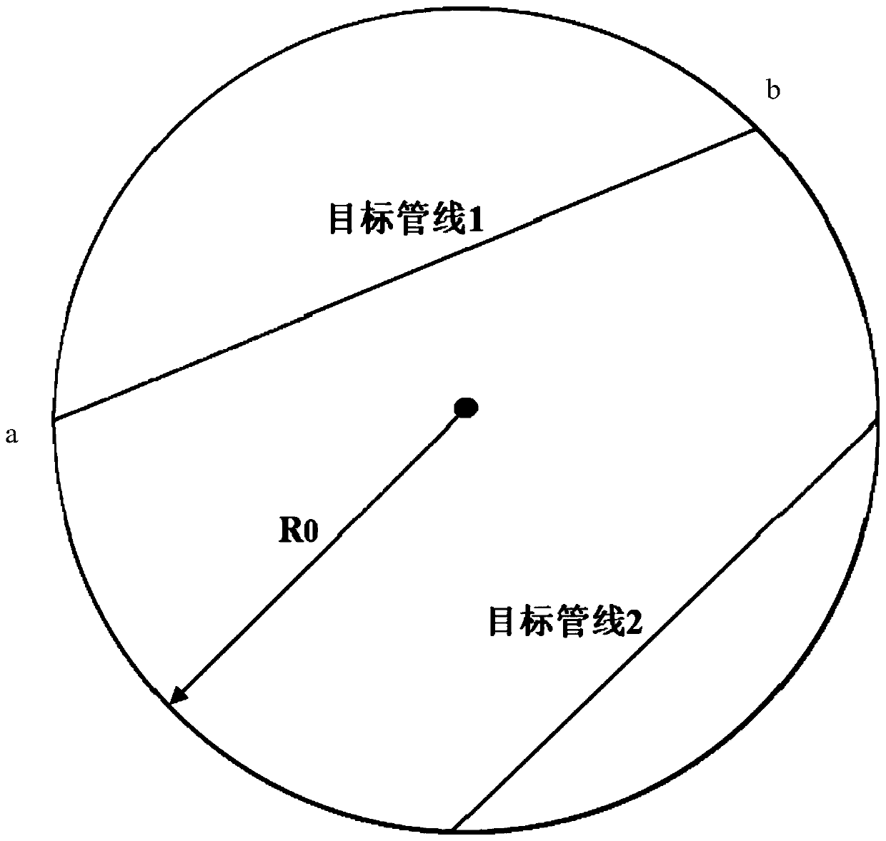
[0034] First, calculate the maximum diffusion rate of natural gas in different soils (sandy soil, loam, clay) according to soil physical parameters, calculate and determine the maximum leakage radius of natural gas, and then based on the natural gas concentration monitored at any position in the soil, or any inspection well or The natural gas concentration is monitored by the silo well, and the two end points of the farthest possible leakage point of the natural gas pipeline from the direct buried pipeline to the monitoring point are determined. This completes the first step, positioning the possible le...

Example Embodiment

[0042] Specific embodiment two: This embodiment is different from the specific embodiment one in that the maximum diffusion radius R in the step one is selected based on the following formula:

[0043] R=vt

[0044] Among them, t is the diffusion time from the leak source to the monitoring point (estimated value, calculated at 24 hours a day and night); v is the diffusion speed of the leaked natural gas in the soil.

[0045] Other steps and parameters are the same as in the first embodiment.

Example Embodiment

[0046] Specific embodiment three: This embodiment is different from specific embodiments one or two in that in the second step, the target pipelines that may be leaked obtained in step one are screened to determine the leaky pipeline; the specific process is:

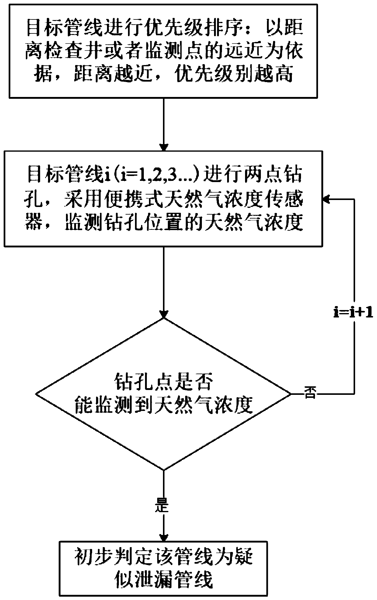
[0047] First, prioritize the target pipelines that may leak in the circle, using the distance from the alarm inspection well or the alarm monitoring point as the standard, and the distance is sorted from small to large, and the order is: i, i+1,..., I ; The target pipeline with a small distance from the monitoring point is prioritized for drilling and excavation; the closer the target pipeline is to the monitoring point, the greater the possibility of leakage of the target pipeline, and the drilling and excavation is preferred;

[0048] First, drill a hole on the ground above the target pipeline i, and use a portable natural gas concentration sensor to monitor the natural gas concentration value at the borehole;

[0049] If th...


PUM


Abstract

The invention discloses a fuel gas direct-buried pipeline leakage point positioning method based on two-point optimizing tracing, relates to a fuel gas direct-buried pipeline leakage point positioningmethod and aims to solve the problems that through existing fuel gas pipeline detecting methods, excavation needs to be repeatedly performed on a direct-buried fuel gas pipeline for looking for leakage points, and consequently high manpower and material resources and large economic losses are caused. The process of the fuel gas direct-buried pipeline leakage two-point optimizing tracing positioning method includes the steps that (1) target pipelines which possibly have leakages are determined; (2) the target pipelines which possibly have leakages are screened, and the leakage pipelines are determined; (3) hole drilling and excavation are performed on the ground above the leakage pipelines in sequence through a two-point method; (4) a concentration diffusion mathematical model of leakage of the leakage pipelines is established, and solving is performed; and (5) gradual two-point optimizing is performed on the leakage pipelines for positioning leakage points. The fuel gas direct-buriedpipeline leakage point positioning method based on two-point optimizing tracing is used for the field of fuel gas direct-buried pipeline leakage point positioning.

Description

technical field [0001] The invention relates to a method for locating the leakage point of a directly buried gas pipeline. Background technique [0002] Urban direct buried gas pipeline is the lifeline of the city and plays an important role in the national economy and industrial production. With the continuous expansion of city size and population growth, the demand for natural gas in cities and towns is increasing, and the scale of natural gas pipelines is also expanding, and the urban buried pipeline network is becoming more and more dense. However, during the operation of natural gas pipelines, factors such as natural aging, corrosion or man-made damage inevitably exist, resulting in leakage accidents from time to time. Since urban natural gas pipelines are mainly laid in densely populated areas and the surrounding environment is relatively complex, once leakage occurs, Accidents such as fire and explosion will cause serious casualties and property losses. According to...

Claims


Application Information

Patent Timeline
IPC IPC(8): F17D5/02
CPCF17D5/02
Inventor 谭羽非王雪梅肖榕
Owner HARBIN INST OF TECH
Why Eureka
Try Eureka