
Phased array receivers and methods employing phase shifting downconverters

a phased array and receiver technology, applied in the direction of antennas, electrical equipment, etc., can solve the problems of high mechanical precision, high cost, and inability to manufacture phase shifters that offer both accuracy and high resolution at rf frequencies, and achieve the effect of reducing the cost and complexity of the phased array transceiver

Inactive Publication Date: 2009-10-08
MCCUNE EARL W JR DR
View PDF0 Cites 25 Cited by
  • Summary
  • Abstract
  • Description
  • Claims
  • Application Information

AI Technical Summary

Benefits of technology

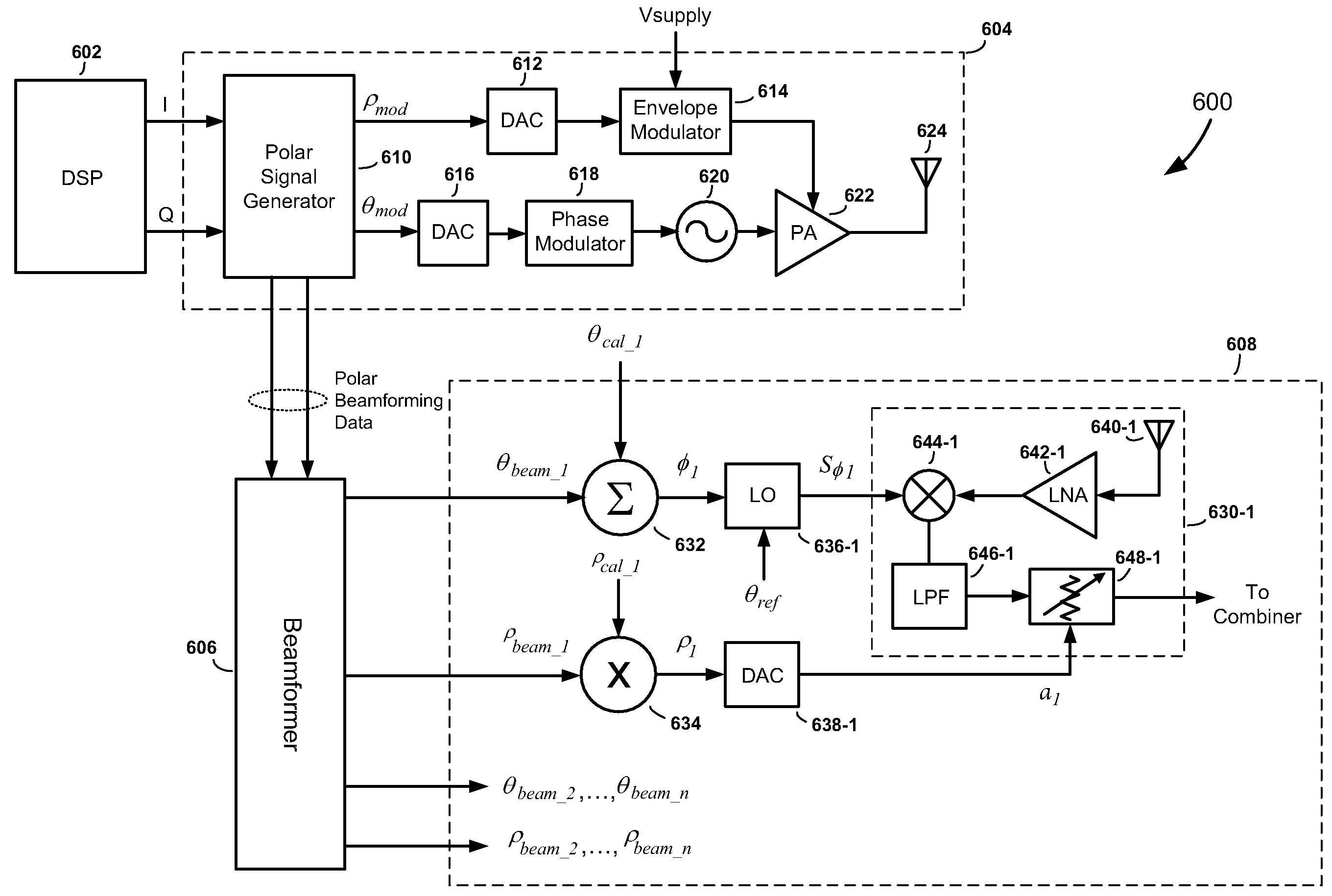
[0011]According to another aspect of the invention, a phased array receiver, similar to the phased array receiver summarized above, is combined with one or more polar modulation transmitters to form a phased array transceiver. The digital phase and gain control signals for the plurality of receive paths of the phased array receiver are provided by one or more polar signal generators of the one or more polar modulation transmitters. The ability to exploit the polar signal generator(s) of the one or more polar modulation transmitters, which would otherwise be operable for the sole purpose of generating the polar modulation signals for the polar modulation transmitter(s), significantly reduces the cost and complexity of the phased array transceiver.

Problems solved by technology

Unfortunately, this high degree of mechanical precision is both time consuming and very expensive.
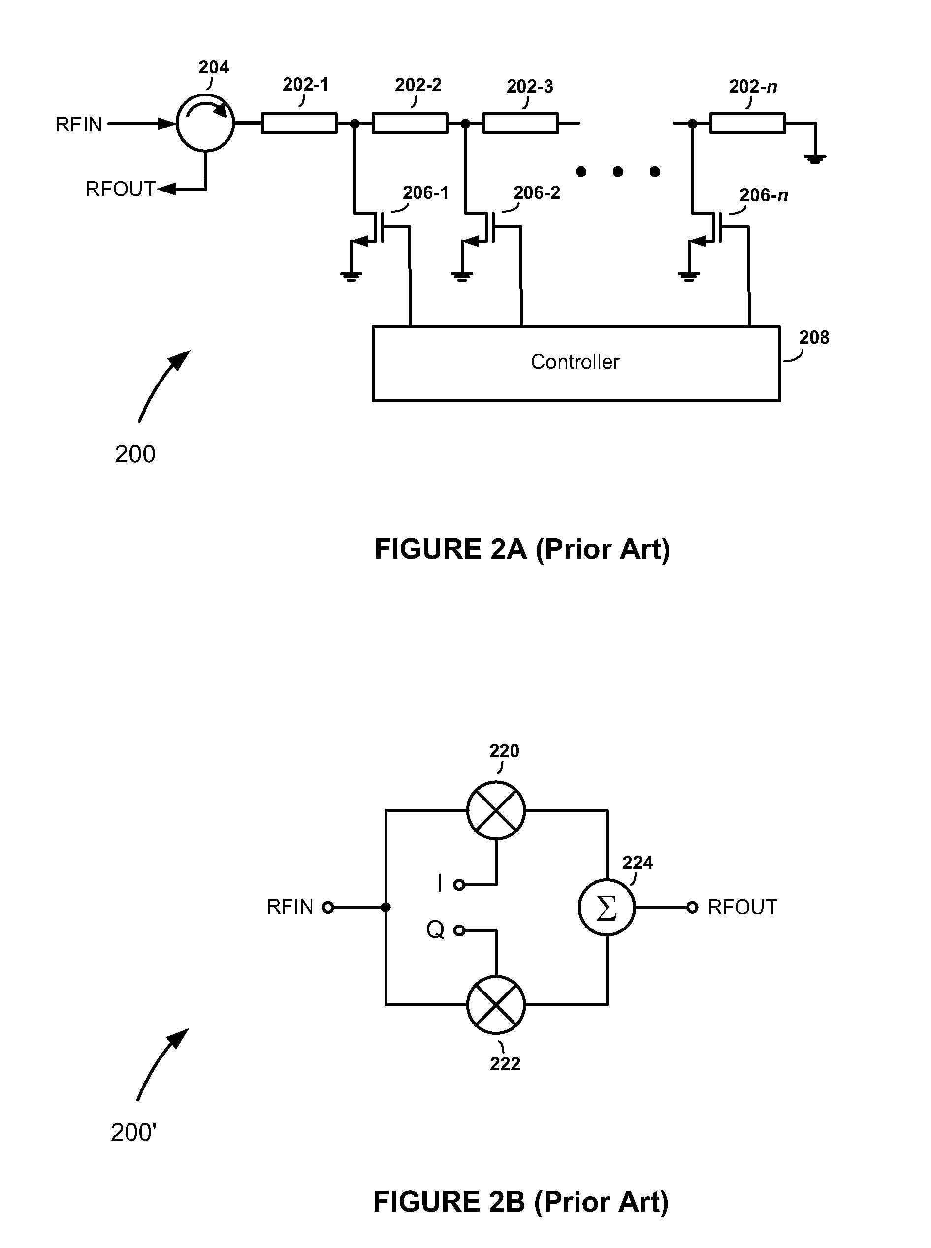
Unfortunately, phase shifters that offer both accuracy and high resolution at RF frequencies, and which are also inexpensive to manufacture, are not readily available.
Although the phase shifter 200′ in FIG. 2B can be controlled with greater resolution than the phase shifter 200 in FIG. 2A, it is not very accurate.

Method used


Image

  • Phased array receivers and methods employing phase shifting downconverters
  • Phased array receivers and methods employing phase shifting downconverters
  • Phased array receivers and methods employing phase shifting downconverters

Examples


Embodiment Construction

[0021]Referring to FIG. 3, there is shown a phased array receiver 300, according to an embodiment of the present invention. The phased array receiver 300 comprises a plurality of receive paths 302-1, 302-2, . . . , 302-n, where n is an integer that is greater than or equal to two, and a combiner 304. The plurality of receive paths 302-1, 302-2, . . . , 302-n includes antenna elements 306-1, 306-2, . . . , 306-n, low-noise amplifiers (LNAs) 308-1, 308-2, . . . , 308-n, downconverters 310-1, 310-2, . . . , 310-n, low-pass filters (LPFs) 312-1, 312-2, . . . , 312-n, and variable gain elements 314-1, 314-2, . . . , 314-n.

[0022]RF signals captured by the antenna elements 306-1, 306-2, . . . , 306-n in the plurality of receive paths 302-1, 302-2, . . . , 302-n are amplified by the LNAs 308-1, 308-2, . . . , 308-n and then coupled to first inputs of the downconverters 310-1, 310-2, . . . , 310-n. As the amplified RF signals are applied to the first inputs of the downconverters 310-1, 310-...


PUM


Abstract

A phased array receiver includes a plurality of receive paths having a plurality of downconverters, a plurality of digitally controlled local oscillators associated with the plurality of receive paths, and a combiner. In response to a plurality of digital phase control signals, the plurality of digitally controlled local oscillators controls phases of a plurality of local oscillator signals generated by the plurality of digitally controlled local oscillators. The phases of the plurality of local oscillator signals are introduced as phase shifts in a plurality of intermediate frequency signals produced by the plurality of downconverters. The plurality of digitally controlled local oscillators is configured to respond to changes in digital values of the plurality of digital phase control signals to achieve a desired phase relationship among the phases of the intermediate frequency signals.

Description

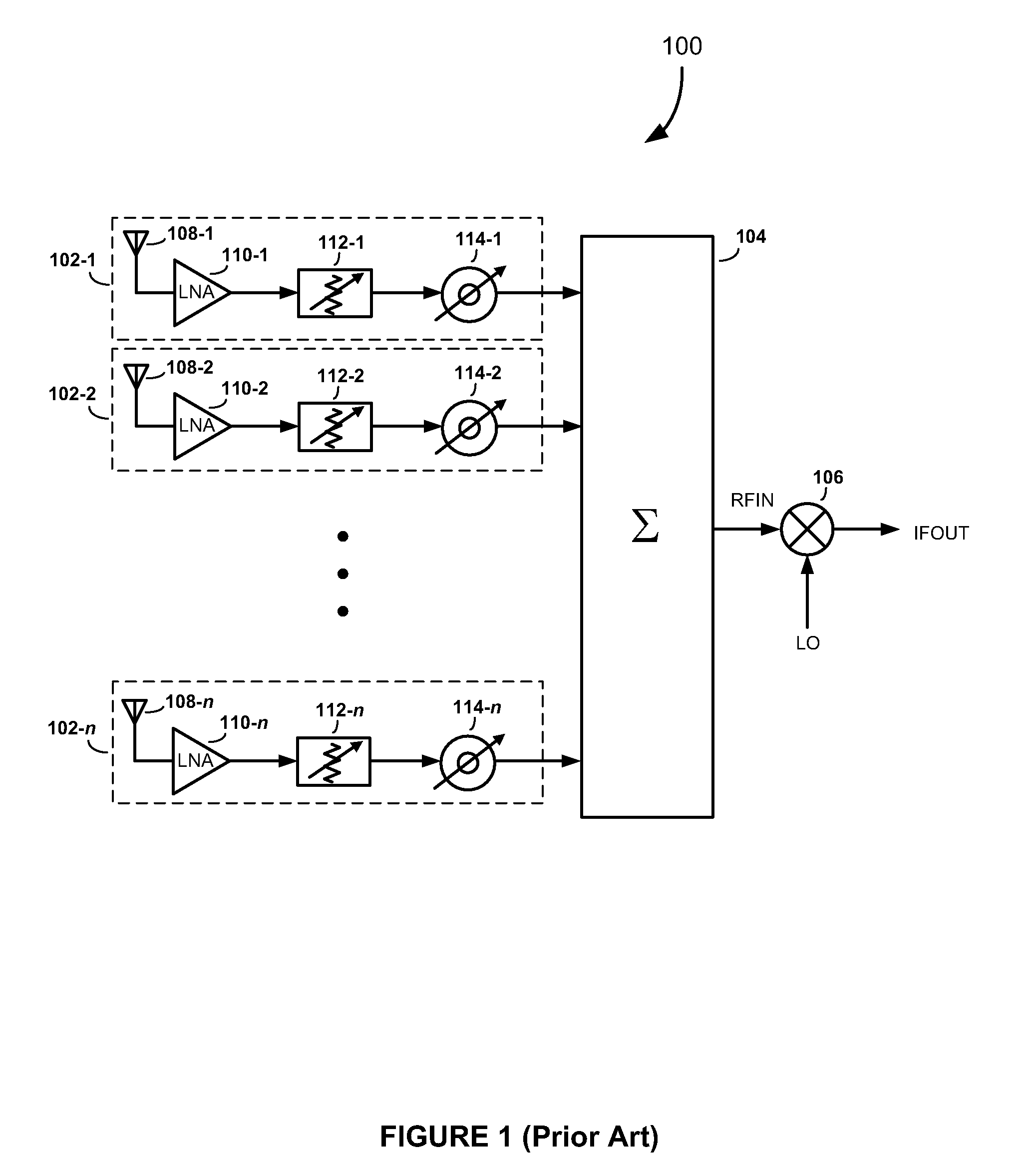
FIELD OF THE INVENTION[0001]The present invention relates generally to phased array receivers. More specifically, the present invention relates to phased array receivers and methods that use digitally controlled phase shifting downconverters.BACKGROUND OF THE INVENTION[0002]Phased array receivers are used in various wireless communications systems to improve the reception of radio frequency (RF) signals. FIG. 1 is a drawing illustrating the principal components of a typical phased array receiver 100. The phased array receiver 100 includes a plurality of receive paths 102-1, 102-2, . . . , 102-n (where n is an integer greater than or equal to two), an RF combiner 104, and a downconverter 106. The plurality of receive paths 102-1, 102-2, . . . , 102-n includes antennas 108-1, 108-2, . . . , 108-n, low noise amplifiers (LNAs) 110-1, 110-2, . . . , 110-n, variable gain elements 112-1, 112-2, . . . , 112-n, and phase shifters 114-1, 114-2, . . . , 114-n. [0003]The amplitudes and phases o...

Claims


Application Information

Patent Timeline
IPC IPC(8): H01Q3/00
CPCH01Q3/38H01Q3/267
Inventor MCCUNE, JR., EARL W.
Owner MCCUNE EARL W JR DR
Learn More