Blade and gas turbine

a gas turbine and blade technology, applied in the field of blades, to achieve the effect of reducing weight, reducing weight, and influencing the strength properties of segments

Inactive Publication Date: 2009-10-08
SIEMENS AG
View PDF11 Cites 18 Cited by
  • Summary
  • Abstract
  • Description
  • Claims
  • Application Information

AI Technical Summary

Benefits of technology

[0010]In an advantageous configuration, a particularly effective connection can be achieved if the base body segment and the edge segment each have a plurality of projections with recesses between them. Then, the projections arranged on one of the two segments can project in a positively locking manner into the opposite recesses in the other segment, forming positively locking toothing. This allows secure attachment of the blade edges in particular in the case of rotor blades, since the centrifugal forces acting on the edge segments in the radial direction during operation can be compensated for by a segment connecting surface of the base body segment running transversely with respect thereto.
[0011]According to a particularly advantageous configuration, a holding pin which runs in the direction of the blade edge secures the segments against relative movements by virtue of this holding pin penetrating transversely through the projections of both segments. The toothed arrangement of the projections results in overlapping, intermeshing regions through which an aligned bore, in which the holding pin is fitted, can extend.
[0012]A further advantageous configuration provides for the segments which form the main blade part to be made from different materials. This is advantageous since there are regions which are subject to higher mechanical stress and regions which are subject to higher thermal stresses, with the result that the main blade part can be optimally matched in its segmented structure to the individual wear conditions by virtue of the different materials. According to further teaching of the invention, some of the segments may be made from a particularly thermally conductive material, and others may be made from a material which is resistant to high temperatures.
[0013]Suitable materials in this context are ceramic material, metals, metal alloys and plastics materials. In addition, further teaching of the invention provides for the segments to be coated. This allows the properties of the segments to be deliberately influenced further.
[0014]To reduce weight, the segments may have cavities. These cavities may in this case be filled with a material which is different from the segment material. This material may, for example, be foams. It is in this way possible to deliberately influence strength properties of the segments.
[0015]It is expedient for the blade to be designed as a guide vane or as a rotor blade. It is particularly advantageous for a blade of this type to be used in a gas turbine.

Problems solved by technology

Furthermore, the modular structure allows the blade edges of the main blade part, which are subject to higher stresses and are accordingly more vulnerable, to be selectively exchanged.

Method used


Image

  • Blade and gas turbine
  • Blade and gas turbine
  • Blade and gas turbine

Examples


Embodiment Construction

[0022]Turbomachines use blade stages, which comprise adjacent rotor blades and guide vanes, to convert flow energy into rotary energy and vice versa. The guide vanes are arranged on the machine housing, while the rotor blades are directly connected to the rotor.

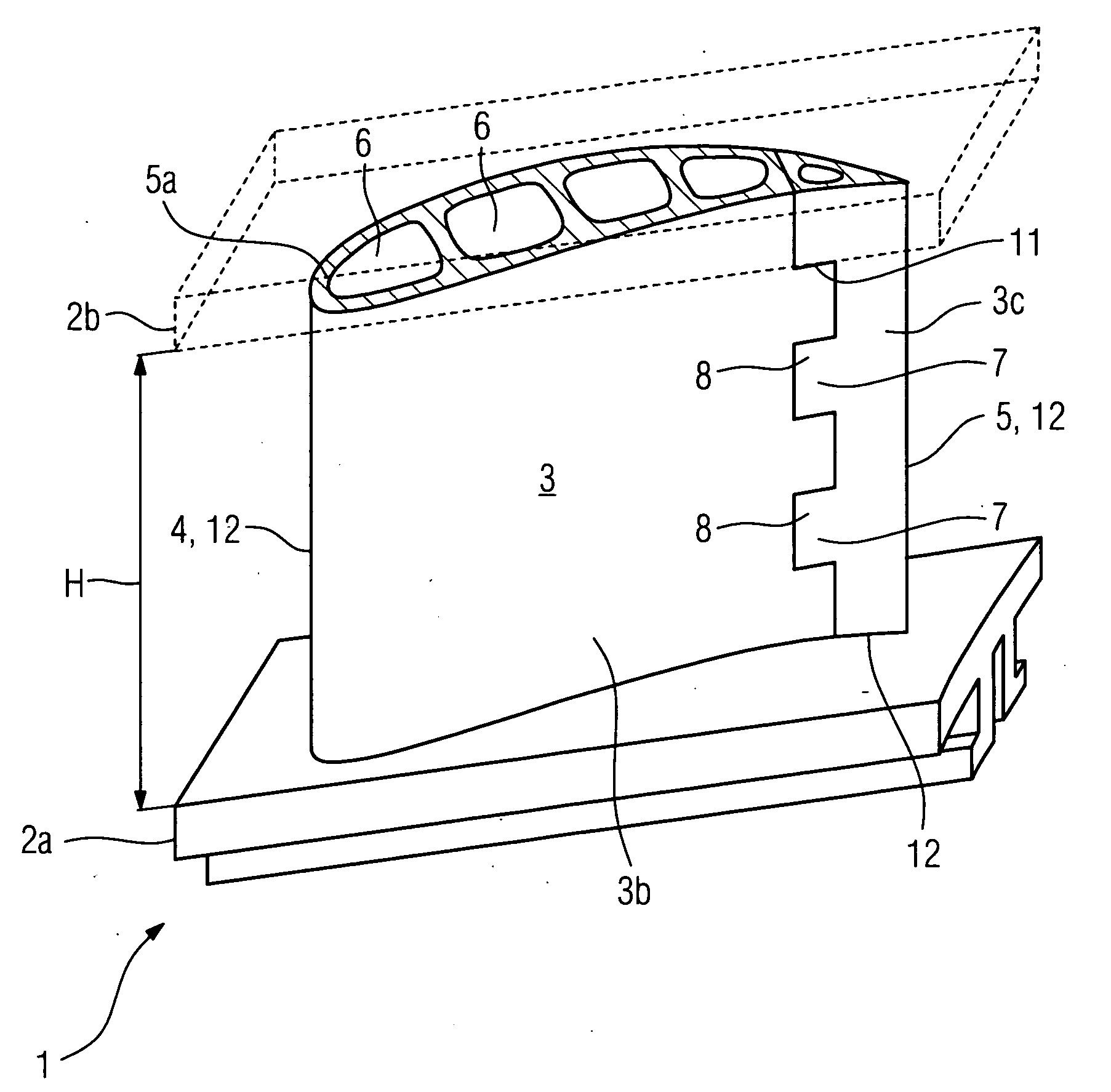
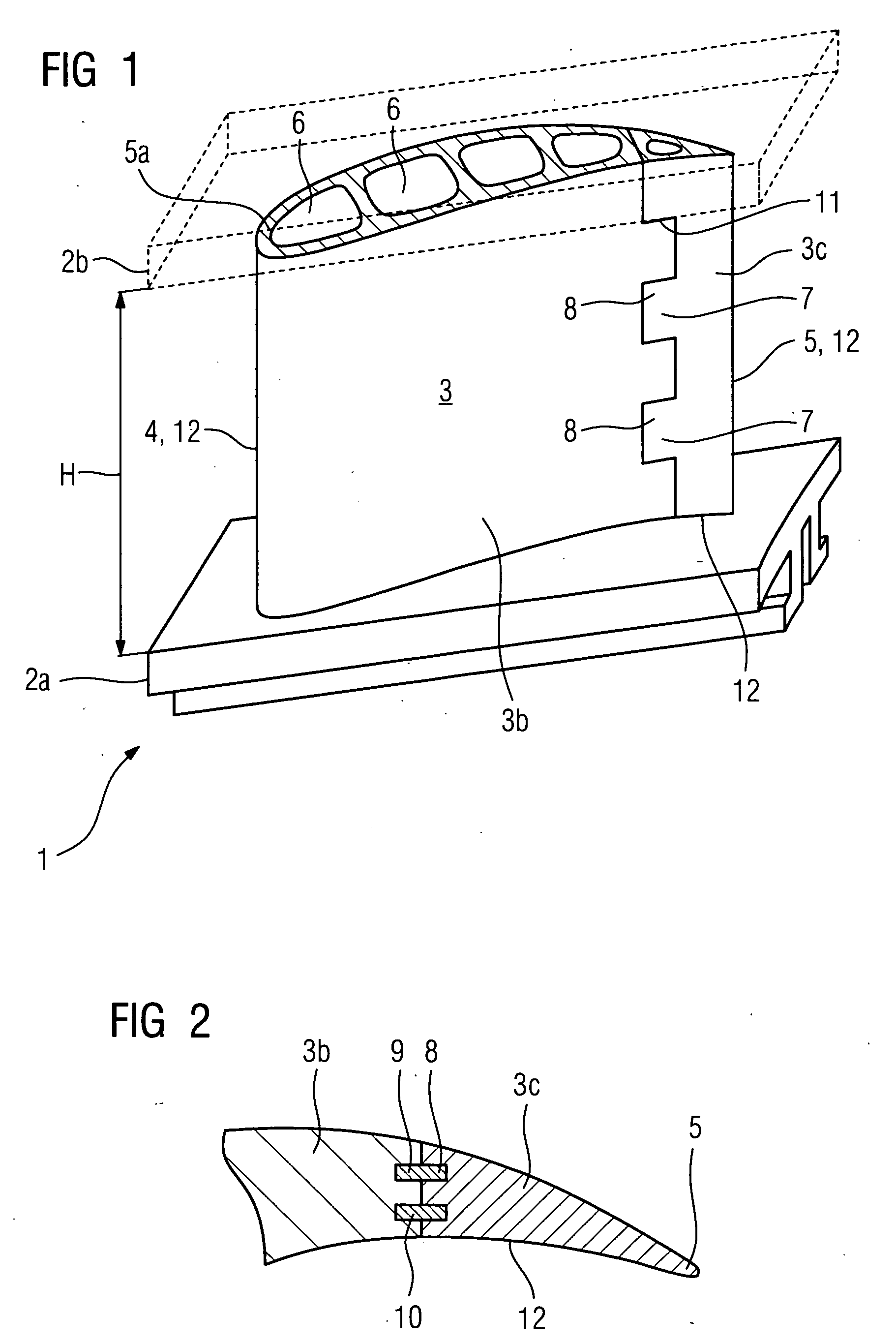
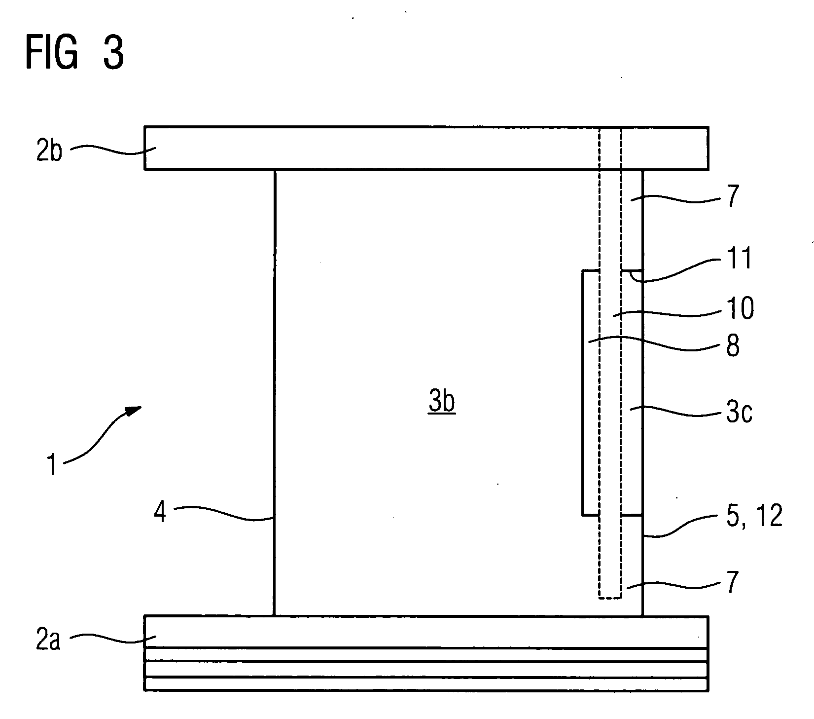
[0023]A blade 1 according to the invention with a segmented trailing edge is illustrated in FIGS. 1 to 3. The blade 1 itself has a platform 2a and a main blade part 3 with a blade leading edge 4 and a blade trailing edge 5. A second platform 2b, which is formed integrally at the upper end 5a of the main blade part 3, is illustrated by dashed lines. The main blade part 3 is composed of a base body segment 3b and a trailing edge segment 3c. As can be seen at the upper end 5a of the main blade part 3, the base body segment 3b has a plurality of cavities 6 which, given sufficient strength, are used to reduce the blade mass in order to lower the mechanical and thermal stresses in operation. One or more cavities 6 may be filled wit...


PUM

PropertyMeasurementUnit
lengthaaaaaaaaaa
heightaaaaaaaaaa
relative movementsaaaaaaaaaa

Abstract

The invention relates to a turbomachine, in particular to a gas turbine and to a method for accelerating a temperature modification of a rotor shaft rotationally mounted in said turbomachine. The aim of said invention is to develop a device and a method for the turbomachine making it possible to reduce the size of a radial split of the turbomachine in order to obtain greater degree of efficiency. The inventive turbomachine comprises a rotor rotationally mounted in the case of the turbomachine, a feeding channel embodied in the rotor for introducing a fluid and an outlet channel embodied in the rotor for removing said fluid. An inlet orifice of the feeding channel is disposed further inside than the outlet orifice of the outlet channel, and means influencing a liquid flow is formed of an actuating device dependent on centrifugal force. Methods for cooling the rotor only by decelerating the gas turbine and for heating the turbomachine rotor by heating fluid flowing therethrough are also disclosed.

Description

CROSS REFERENCE TO RELATED APPLICATION[0001]This application is the US National Stage of International Application No. PCT / EP2004 / 005753, filed May 27, 2004 and claims the benefit thereof. The International Application claims the benefits of European Patent application No. 03013857.2 EP filed Jun. 18, 2003, both of the applications are incorporated by reference herein in their entirety.FIELD OF THE INVENTION[0002]The invention relates to a blade for use in turbomachines, having a blade root, a platform region and a main blade part, which main blade part has a blade length from a blade leading edge to a blade trailing edge and a blade height from the platform region to a main blade part tip, and which is formed from at least one base body segment and, in the region of at least one of the two blade edges, from at least one edge segment which is connected in a positively locking manner to the base body segment.BACKGROUND OF THE INVENTION[0003]A corresponding turbine blade of modular co...

Claims


Application Information

Patent Timeline
Patent Type & Authority Applications(United States)
IPC IPC(8): F01D5/14B23P15/04F01D5/28
CPCB23P15/04F01D5/14F05D2230/61F01D5/282F01D5/284F01D5/147
Inventor AHMAD, FATHIBUCHAL, TOBIASDANKERT, MICHAELLANG, GERNOTSCHEURLEN, MICHAEL
Owner SIEMENS AG
Why Eureka
Try Eureka