Fuel reformer

a fuel reformer and fuel technology, applied in chemical/physical processes, physical/chemical process catalysts, chemical apparatus and processes, etc., can solve the problems of increasing weight and manufacturing costs, heat loss, and inability to increase the amount of hydrogen produced, so as to improve the efficiency of fuel reforming and reduce the cost of manufacturing. , the effect of improving the efficiency of fuel reform

Inactive Publication Date: 2009-10-08
PRECISION COMBUSTION +1
View PDF20 Cites 26 Cited by
  • Summary
  • Abstract
  • Description
  • Claims
  • Application Information

AI Technical Summary

Benefits of technology

[0031]The present invention provides a fuel reformer that can efficiently reform fuel with superior star

Problems solved by technology

With reactors relying on this reaction, the site in which the partial oxidation occurs is exposed to the remarkably high temperature of nearly 1000° C. For this reason, a heat-resistant metal should be used, which leads to an increase in weight as well as manufacturing cost.
Simultaneously, since the temperature of the catalytic converter increases, it is necessary to restrict the amount of fuel injected and the amou

Method used


Image

  • Fuel reformer
  • Fuel reformer
  • Fuel reformer

Examples


Embodiment Construction

[0036]An embodiment of the present invention is described hereafter with reference to the drawings. However, the present invention is not limited thereto.

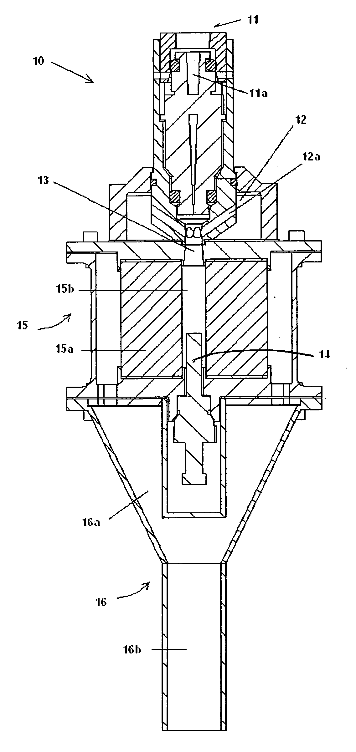
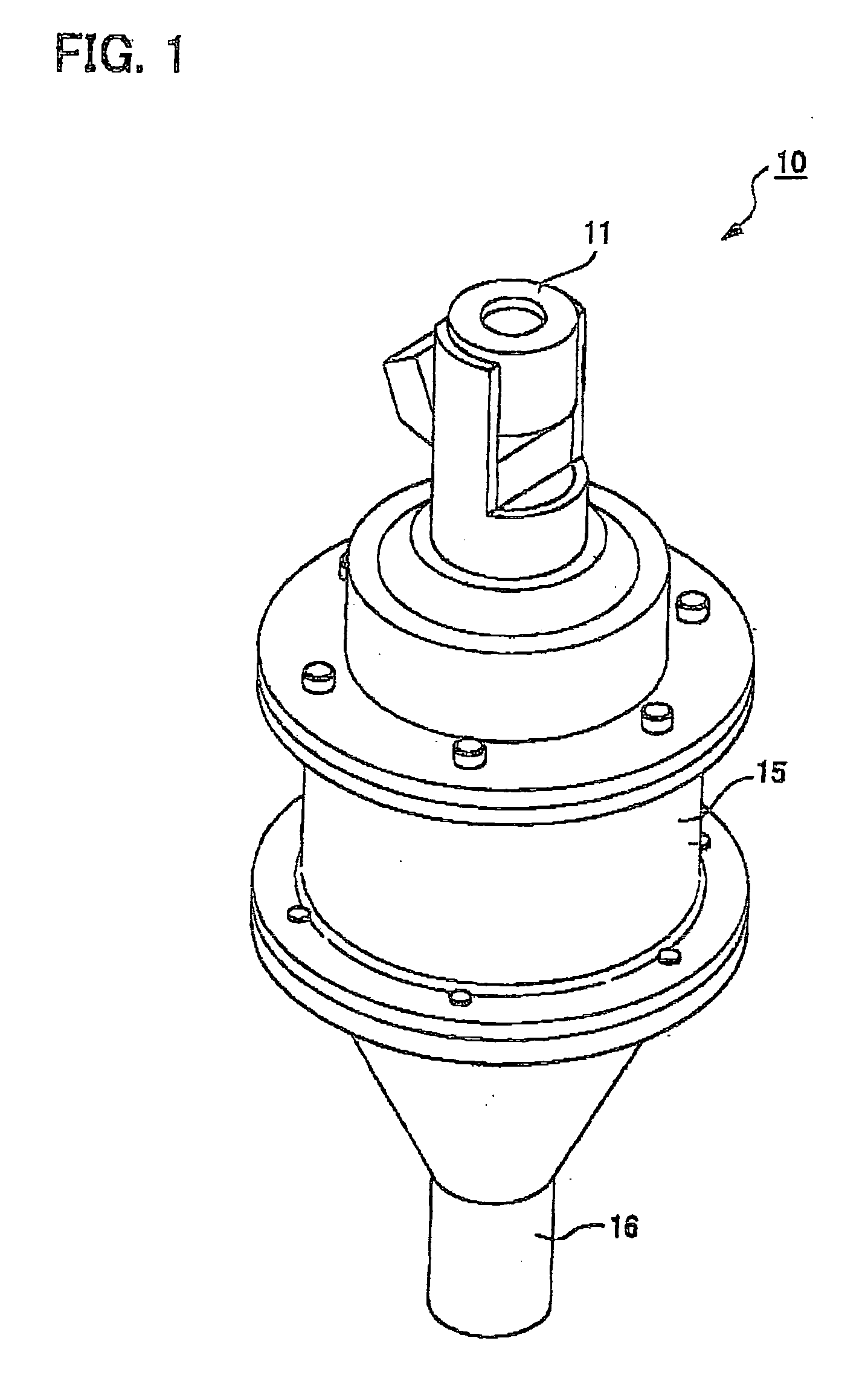
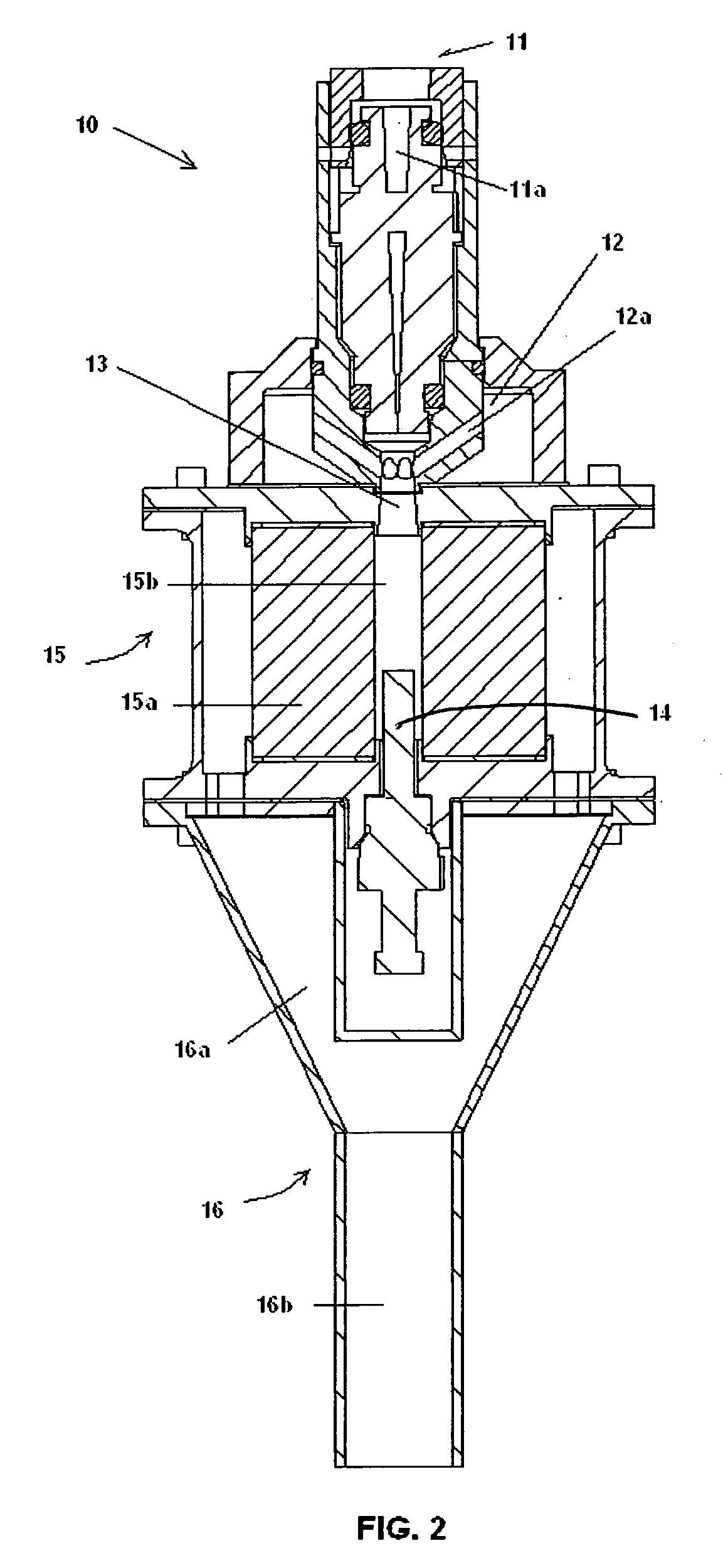
[0037]FIG. 1 is a perspective view illustrating a fuel reformer 10 according to an embodiment of the present invention, and FIG. 2 is a longitudinal sectional view illustrating the fuel reformer according to the embodiment. Referring to FIGS. 1 and 2, the fuel reformer 10 includes a reforming portion 15 for reforming fuel by way of an oxidizer to generate hydrogen-rich fuel gas. Specifically, the fuel reformer 10 includes a fuel inlet portion 11 for introducing fuel, an oxidizer inlet portion 12 for introducing an oxidizer, a mixer 13 for mixing the fuel and oxidizer introduced, a supply portion or communication passage 15b for supplying fuel and oxidizer mixed in the mixer 13 into the reforming portion 15, and an outlet portion 16 for discharging hydrogen-rich fuel gas generated in the reforming portion 15.

[0038]The fuel inlet por...


PUM

PropertyMeasurementUnit
Velocityaaaaaaaaaa
Velocityaaaaaaaaaa
Velocityaaaaaaaaaa

Abstract

A fuel reformer includes a reforming portion having a tubular catalytic converter that is composed of a substrate supporting the catalytic component, and is arranged to have a center axis extending along the supply direction of the fuel and oxidizer derived from a supply portion, and a communication passage arranged along an inner wall of the catalytic converter and communicating with the supply portion. The fuel and oxidizer supplied from the supply portion to the communication passage pass from the inner wall of the catalytic converter to an outer wall thereof by forced convection, thereby reforming the fuel.

Description

BACKGROUND OF THE INVENTION[0001]1. Field of the Invention[0002]The present invention relates to fuel reformers for reforming fuel to produce hydrogen-rich gas, and more particularly, to fuel reformers that can efficiently reform fuel with superior startability, low manufacturing cost, and small size.[0003]2. Related Art[0004]Hydrogen is a clean energy fuel that has received considerable attention as a future alternative fuel to oil. Research is advancing hydrogen as an energy source in applications such as fuel cells, and internal combustion engines. Particularly, in addition to research of hydrogen applications as an energy source for hydrogen engines and hydrogenation engines, much effort has been invested in the research of applying hydrogen as a reducing agent for purifying harmful waste gases such as NOx and SOx. Thus, a considerable amount of research has been conducted for the advancement of hydrogen use in recent years, and at the same time, various methods are being examin...

Claims


Application Information

Patent Timeline
IPC IPC(8): B01J8/06
CPCB01J8/025C01B2203/82B01J2208/00309B01J2208/00407B01J2208/00557B01J2208/00716C01B3/382C01B2203/0244C01B2203/0261C01B2203/0811C01B2203/085C01B2203/1005C01B2203/1064C01B2203/1082C01B2203/1235C01B2203/1282C01B2203/1294C01B2203/169B01J8/0492
Inventor ROYCHOUDHURY, SUBIRSPENCE, DAVIDMASTANDUNO, RICHARDWALSH, DENNIS E.IWAMOTO, JUNMOTOHASHI, GOMIKAMI, HITOSHIWALKER, ERIC
Owner PRECISION COMBUSTION
Why Eureka
Try Eureka