Engine

a technology of engine and compression, applied in the field of engines, can solve the problems of difficult suppression of difficult to suppress knocking or accidental fire, etc., and achieve the effect of efficiently reforming the fuel, and reducing the amount of heat in the reforming fuel

Active Publication Date: 2019-01-08
YANMAR POWER TECHNOLOGY CO LTD
View PDF16 Cites 0 Cited by
  • Summary
  • Abstract
  • Description
  • Claims
  • Application Information

AI Technical Summary

Benefits of technology

[0013]As the effects of the present invention, the following advantageous effects are provided.
[0014]According to one aspect of the present invention, the fuel is reformed to the lower hydrocarbon fuel, in which the knocking is unlikely to occur, through the use of characteristics of the EGR gas, and the fuel is mixed with the intake air, so that the fuel and the intake air are uniformly and leanly mixed. Accordingly, the occurrence of the knocking or the accidental fire is suppressed, which makes it possible to perform the operations of the premixed compression self-ignition.
[0015]According to another aspect of the present invention, the additional amount of heat is eliminated from the reforming fuel. Accordingly, the occurrence of the knocking or the accidental fire is suppressed, which makes it possible to perform the operations of the premixed compression self-ignition.
[0016]According to another aspect of the present invention, the EGR gas and the fuel are uniformly mixed in a period from the injection of the fuel to the start of the adiabatic compression, thereby efficiently reforming the fuel. Accordingly, the occurrence of the knocking or the accidental fire is suppressed, which makes it possible to perform the operations of the premixed compression self-ignition.
[0017]According to another aspect of the present invention, when the ignitability in the output cylinder is in a low state, the ignition is assisted. Accordingly, the occurrence of the knocking or the accidental fire is suppressed, which makes it possible to perform the operations of the premixed compression self-ignition.
[0018]According to another aspect of the present invention, the EGR gas and the fuel are uniformly mixed until the adiabatic compression is started, thereby efficiently reforming the fuel. Accordingly, the occurrence of the knocking or the accidental fire is suppressed, which makes it possible to perform the operations of the premixed compression self-ignition.

Problems solved by technology

Also, even when the fuel and the intake air are uniformly, leanly mixed, there is a high possibility that knocking or an accidental fire occurs due to change in terms of an elapsed time from the start time of start-up operation, engine load, an air-fuel ratio, and the like.
Accordingly, there is a disadvantage in that it is difficult to suppress the occurrence of the knocking or the accidental fire only based on the timing (quantity or density) of mixing the EGR gas.

Method used


Image

  • Engine
  • Engine
  • Engine

Examples


first embodiment

[0025]Hereinafter, an engine 1 according to the present invention will be described referring to FIGS. 1 and 2.

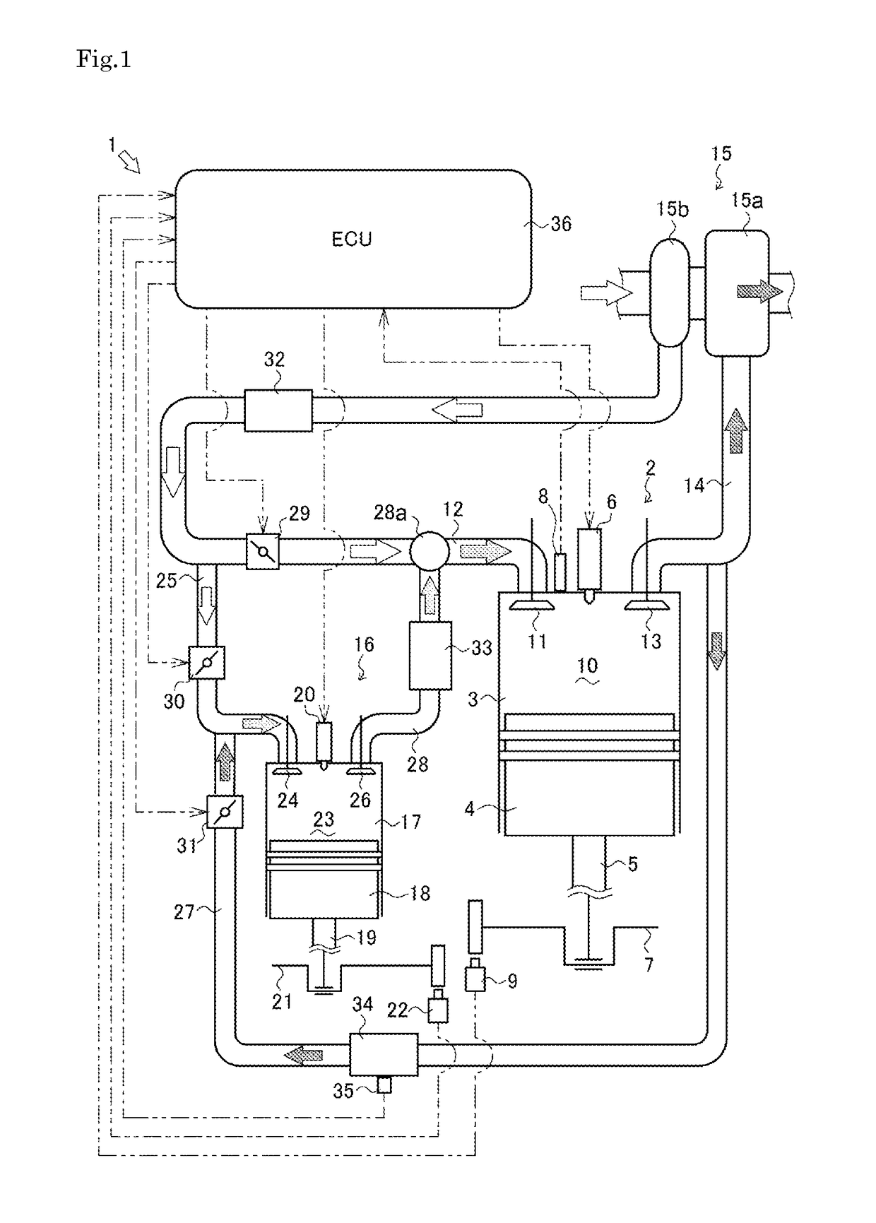
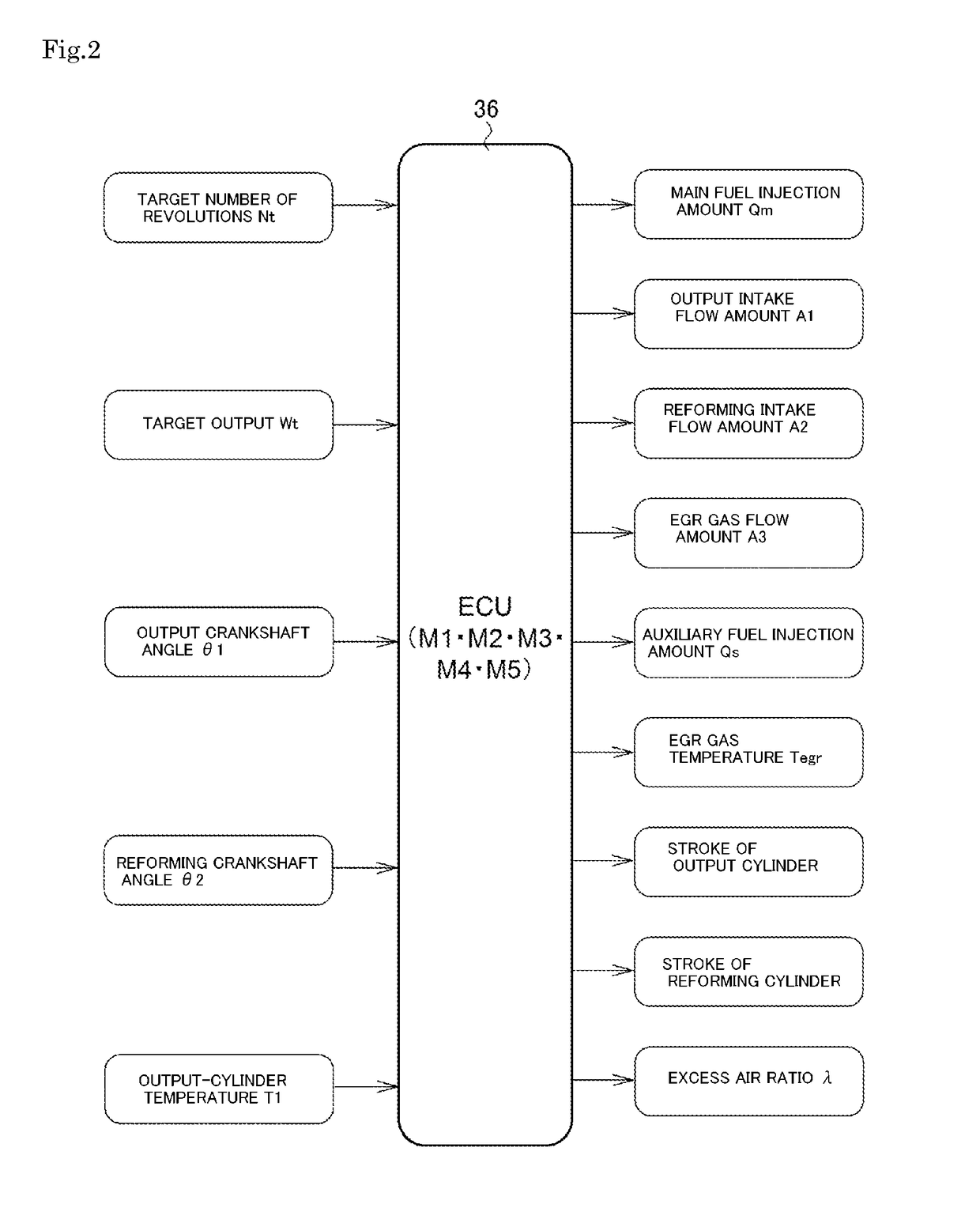
[0026]As illustrated in FIG. 1, the engine 1 is a diesel engine run on light oil or heavy oil as fuel. The engine 1 mainly includes an output cylinder 2, a supercharger 15, a reforming cylinder 16 that serves as a fuel reforming device, an intake intercooler 32, a reforming fuel intercooler 33, an EGR gas intercooler 34, and an ECU 36 as a control device.

[0027]The output cylinder 2 serves to generate power by the combustion of fuel and transmit the power to an output shaft. The output cylinder 2 includes an output cylinder 3, an output piston 4, an output connecting rod 5, and an auxiliary fuel injection device 6.

[0028]Regarding the output cylinder 2, the output piston 4 is slidably inserted into the interior of the output cylinder 3. The output cylinder 3 is configured such that one side thereof is blocked by a cylinder head not illustrated, and the other side thereof is o...

second embodiment

[0073]Next, the engine 1 of the engine 1 according to the present invention will be described referring to FIG. 6. It is noted that, in the embodiment described below, regarding the same matters of the embodiments that have been already described, their specific descriptions are omitted, and the following description focuses on the different matters.

[0074]A supply pipe 40 is connected to the reforming cylinder 16 via the reforming intake valve 24, and an exhaust pipe 28 is connected to the reforming cylinder 16 via the reforming exhaust valve 26. The supply pipe 40 is connected to the intake pipe 12. Also, the supply pipe 40 is connected to the exhaust pipe 14 via the EGR pipe 27. That is, it is configured such that part of the exhaust gas from the combustion chamber 10 of the output cylinder 2 can be supplied to the supply pipe 40 as the EGR gas via the EGR pipe 27. Furthermore, the primary fuel injection device 20 that can inject the fuel is provided in the supply pipe 40. The exh...


PUM


Abstract

Provided is an engine that suppresses the occurrence of knocking or an accidental fire, which makes it possible to perform the operations of premixed compression self-ignition. Regarding the present invention, an engine includes a reforming cylinder, which is a fuel reforming device, and the reforming cylinder is connected to an intake pipe and an EGR pipe via a supply pipe and connected to the intake pipe via an exhaust pipe, and a primary fuel injection device is provided that injects fuel to the mixture of intake air and exhaust gas supplied to the reforming cylinder through the supply pipe.

Description

[0001]This is the U.S. national stage of application No. PCT / JP2014 / 050479, filed on Jan. 14, 2014. Priority under 35 U.S.C. § 119(a) and 35 U.S.C. § 365(b) is claimed from Japanese Application No. 2013-004699, filed Jan. 15, 2013, the disclosure of which is also incorporated herein by reference.TECHNICAL FIELD[0002]The present invention relates to an engine and more particularly relates to a premixed compression ignition engine.BACKGROUND ART[0003]Conventionally, there have been known premixed compression ignition engines as engines that compress fuel under high pressure in a lean state and lead to self-ignition and combustion, thereby achieving the small amount of smoke and the small amount of NOx. The premixed compression ignition engine is configured to compress air-fuel mixture under high pressure in a combustion chamber and carry out self-ignition and combustion.[0004]The premixed compression ignition engine is required to uniformly and leanly mix the fuel with intake air. Als...

Claims


Application Information

Patent Timeline
Patent Type & Authority Patents(United States)
IPC IPC(8): F02M26/19F02D41/00F02D19/06F02B51/00F02M35/108F02B1/12F02M26/34F02M26/36F02M31/08F02M26/05F02B29/04F02M31/20F02M26/28
CPCF02B1/12F02B51/00F02D19/0671F02D41/0025F02M26/34F02M26/36F02M26/19F02M35/108Y02T10/36F02B29/0406F02M26/05F02M26/28F02M31/08F02M31/20F02B7/00F02B33/22F02B37/04F02M26/08F02B73/00F02D25/00Y02T10/30
Inventor ASAI, GOU
Owner YANMAR POWER TECHNOLOGY CO LTD
Why Eureka
Try Eureka