Control method of catalyst activity

a technology of catalyst activity and control method, which is applied in the direction of physical/chemical process catalysts, other chemical processes, separation processes, etc., can solve the problems of reducing the number of effective active spots, reducing the efficiency of hydrogen production, and reducing the speed of the reaction, so as to achieve efficient re-usability, efficient manufacturing, and efficient re-usability.

Inactive Publication Date: 2005-10-27
HONDA MOTOR CO LTD
View PDF2 Cites 0 Cited by
  • Summary
  • Abstract
  • Description
  • Claims
  • Application Information

AI Technical Summary

Benefits of technology

[0008] The present invention is made in consideration of the above problems, and its object is to provide a method able to remove the coke and the unreacted component deposited in the active spot on the catalyst surface and restore the reduced catalyst activity to efficiently reform the fuel for an automobile for a long time.
[0011] restraining deterioration of the catalyst by burning off coke and an unreacted component deposited on the surface of said catalyst by said reforming reaction under the existence of oxygen enrichment air.
[0016] According to the present invention, the catalyst activity reduced by the reforming reaction can be approximately perfectly restored and the fuel for an automobile can be efficiently reformed for a long time and hydrogen can be efficiently manufactured. Further, the following effects are recognized. Firstly, activity deterioration of the catalyst can be restrained since accumulation of the coke in the active spot on the catalyst surface is reduced. Secondly, since the coke can be perfectly removed, a pressure loss of the catalyst can be restrained and LHSV (liquid hourly space velocity=spatial velocity of fuel per one hour) can be increased. Thirdly, the using amount of the catalyst can be reduced since the catalyst deterioration can be restrained and duration of the catalyst activity can be increased. Since the used catalyst amount can be reduced, the using amount of a noble metal can be reduced and cost can be reduced. Further, it is possible to design a compact reactor. Fourthly, since the coke can be perfectly removed even when the coke is deposited, it is not necessary to supply a surplus amount of oxidizer (steam, oxygen and air) to a reactor. For example, the present invention solves the problem that thermal efficiency is reduced and more energy is required to obtain hydrogen when the steam is superfluously supplied. The present invention also solves the problem that hydrogen yield is reduced due to excessive combustion when oxygen is superfluously supplied. The present invention also solves the problem that the unreacted oxidizer must be separated and recovered from hydrogen when the surplus amount of oxidizer is supplied.

Problems solved by technology

However, when the reforming reaction is continuously performed, the disadvantage that a carbonaceous material called coke is deposited and accumulated on the surface of the catalyst and the number of effective active spots is reduced is caused.
Therefore, this disadvantage becomes a great obstacle in realizing the efficient manufacture of hydrogen.
However, as the catalyst activity is weakened, a reaction velocity is reduced so that no efficient reforming reaction can be performed.
However, when a fixed bed flow reactor is used, etc., its processing is difficult (see Non-Patent Document 1).
No catalyst causing no coking has been developed yet.
However, when the steam is superfluously supplied, thermal efficiency is reduced and more energy is required to obtain hydrogen.
When oxygen is superfluously supplied, the yield of hydrogen is reduced due to excessive combustion.
Further, when a surplus amount of oxidizer is supplied, an unreacted oxidizer must be separated and recovered from hydrogen.
Accordingly, no method able to effectively prevent the deposition of the coke on the catalyst surface and control efficiency of the reforming reaction is established in the present situation.

Method used


Image

  • Control method of catalyst activity
  • Control method of catalyst activity

Examples


embodiment

[0029] The present invention will next be explained in detail on the basis of an example, but the present invention is not limited to this example.

example

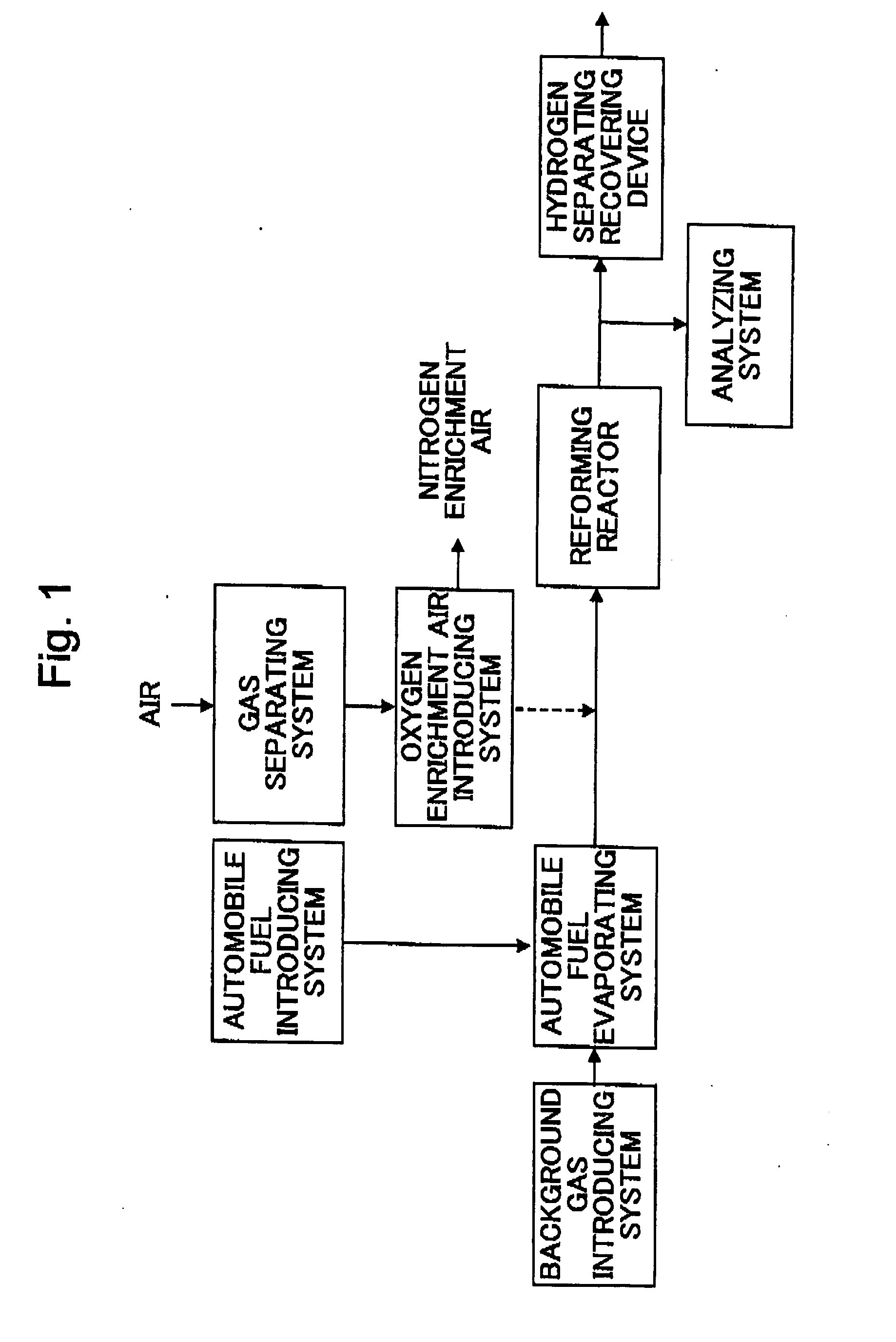
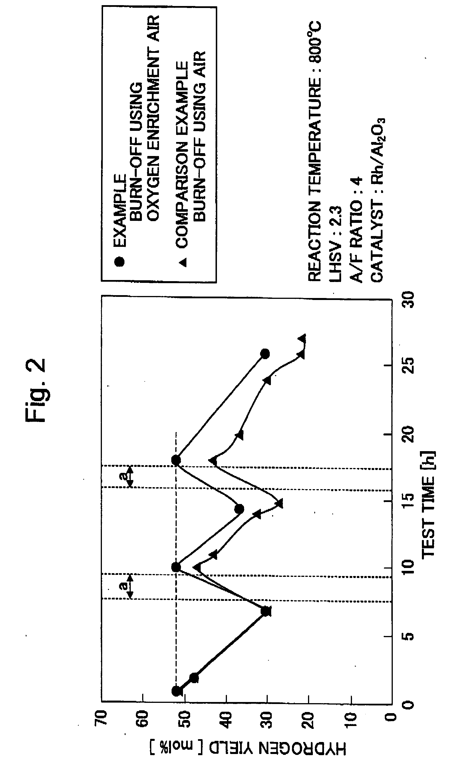
[0030] The reforming using the partial oxidizing reaction of diesel fuel was performed and coke and an unreacted component deposited on the catalyst surface by this reforming reaction were burned off by using the oxygen enrichment air. The hydrogen manufacturing device of the continuous type was used as a hydrogen manufacturing device, and a partial oxidizing catalyst Rh / Al2O3 was used as the catalyst.

[Preparation of Partial Oxidizing Catalyst Rh / Al2O3]

[Preparation of γAl2O3]

[0031] About 100 g of prepared γAl2O3 (AKP-G30LA manufactured by Sumitomo Kagaku Co., Ltd.) was suspended to 200 mL of super pure water within a beaker for storing 500 mL. A stirrer piece manufactured by Teflon (registered trademark) was put into the suspended solution, and was slowly agitated for several minutes at room temperature by a magnetic stirrer with a hot plate. After the agitation, water was removed and the above operation was repeated three times. γAl2O3 performed three times with respect to the a...


PUM

PropertyMeasurementUnit
weight ratioaaaaaaaaaa
temperatureaaaaaaaaaa

Abstract

The invention provides a method able to remove coke and an unreacted component deposited in an active spot on the surface of a catalyst and restore reduced catalyst activity to efficiently reform fuel for an automobile for a long time. The catalyst activity can be approximately perfectly restored by burning-off the coke and the unreacted component deposited on the surface of the catalyst by using oxygen enrichment air.

Description

CROSS-REFERENCE TO RELATED APPLICATIONS [0001] This application is based upon and claims the benefit of priority from the prior Japanese Patent Application No. 2004-075941 filed on Mar. 17, 2004, the entire contents of which is incorporated herein by reference. FIELD OF THE INVENTION [0002] The present invention relates to a method for controlling catalyst activity in a reforming reaction of automobile fuel using a catalyst. BACKGROUND OF THE INVENTION [0003] Hydrogen energy is clean energy and its future utilization is expected as an energy source such as a fuel cell, an internal combustion engine, etc. With respect to the internal combustion engine, researches with respect to a hydrogen engine, a hydrogen addition engine, de-NOx with hydrogen as a reducer, etc. are made. Further, with respect to the supply of hydrogen as a raw material of the fuel cell, a research development about a manufacturing method of hydrogen using fuel reforming is vigorously performed. [0004] Various kind...

Claims


Application Information

Patent Timeline
Patent Type & Authority Applications(United States)
IPC IPC(8): B01J23/46B01J23/96B01J38/00B01J38/12B01J38/14C01B3/38H01M4/90H01M8/22
CPCB01J23/464B01J23/96B01J38/12C01B2203/1247C01B3/386C01B2203/0261C01B2203/1064B01J38/16Y02P20/52Y02P20/584
Inventor KABASHIMA, HAJIMEIWAMOTO, JUNOKU, MASARU
Owner HONDA MOTOR CO LTD
Why Eureka
Try Eureka