Automated heat exchanger tube cleaning assembly and system

a technology of heat exchanger tube and cleaning assembly, which is applied in the direction of cleaning using liquids, distance measurement, instruments, etc., can solve the problem of remote location of the motion control computer

Active Publication Date: 2009-10-15
HYDROCHEM
View PDF18 Cites 37 Cited by
  • Summary
  • Abstract
  • Description
  • Claims
  • Application Information

AI Technical Summary

Benefits of technology

[0008]In accordance with the illustrative embodiments hereinafter described, an automated heat exchanger tube cleaning assembly and system are provided. In an embodiment, the system can automatically (without ongoing human intervention) survey the tube sheet of a heat exchanger in three dimensions, convert and record the survey results as a digital file in three dimensions, and then, according to sequential parameters input via custom software, automatically coordinate via computer one or more cleaning devices such as lances to effect the cleaning of each desired tube of the heat exchanger.

Problems solved by technology

Further, the location of the motion control computer may be remote from the location of the tube cleaning device.

Method used


Image

  • Automated heat exchanger tube cleaning assembly and system
  • Automated heat exchanger tube cleaning assembly and system
  • Automated heat exchanger tube cleaning assembly and system

Examples


Embodiment Construction

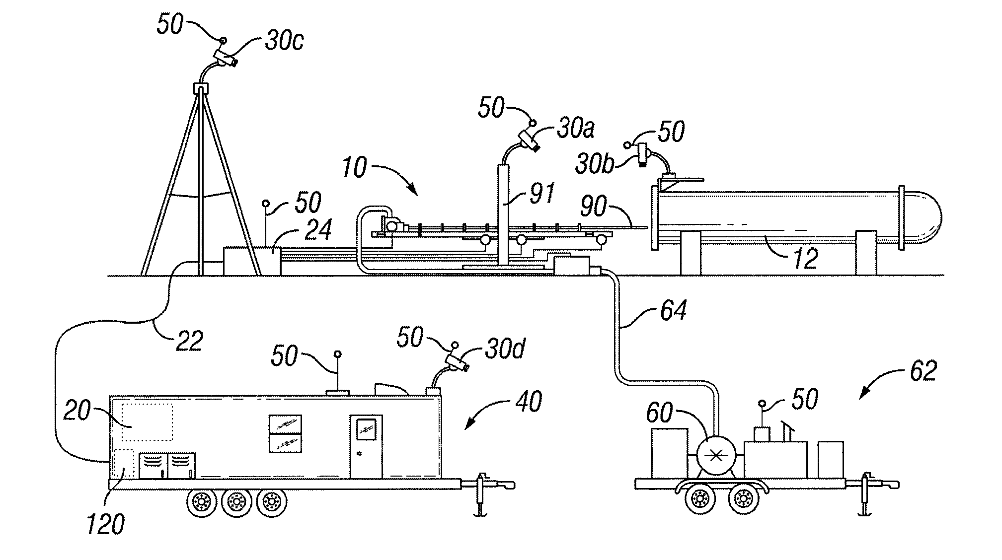
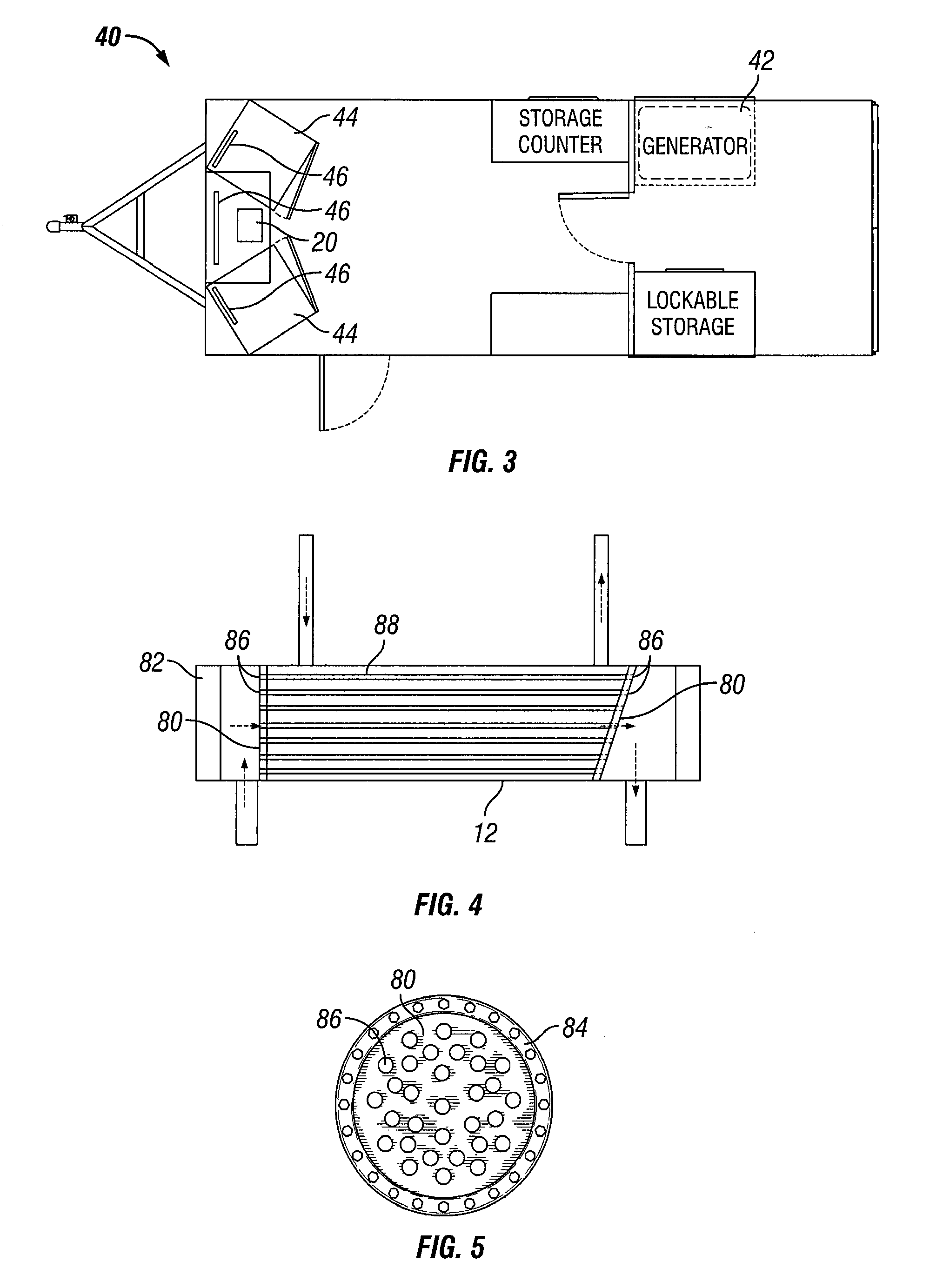
[0043]Referring now to FIG. 1, an illustrative embodiment of an automated heat exchanger tube cleaning assembly 10 and related system is provided. Assembly 10 allows for automated tube lancing of a heat exchanger 12 or other piping or equipment used in an industrial facility such as, for example, a petrochemical plant or oil refinery. Assembly 10 is positioned adjacent exchanger 12 to be cleaned. Assembly 10 can facilitate the delivery of one or more streams of cleaning materials such as high-pressure water and / or chemicals to the inside of tubes 88 (see FIG. 4) inside exchanger 12. The pressurized cleaning stream removes residue build-up from the inside of these tubes 88 as well as other affected areas.

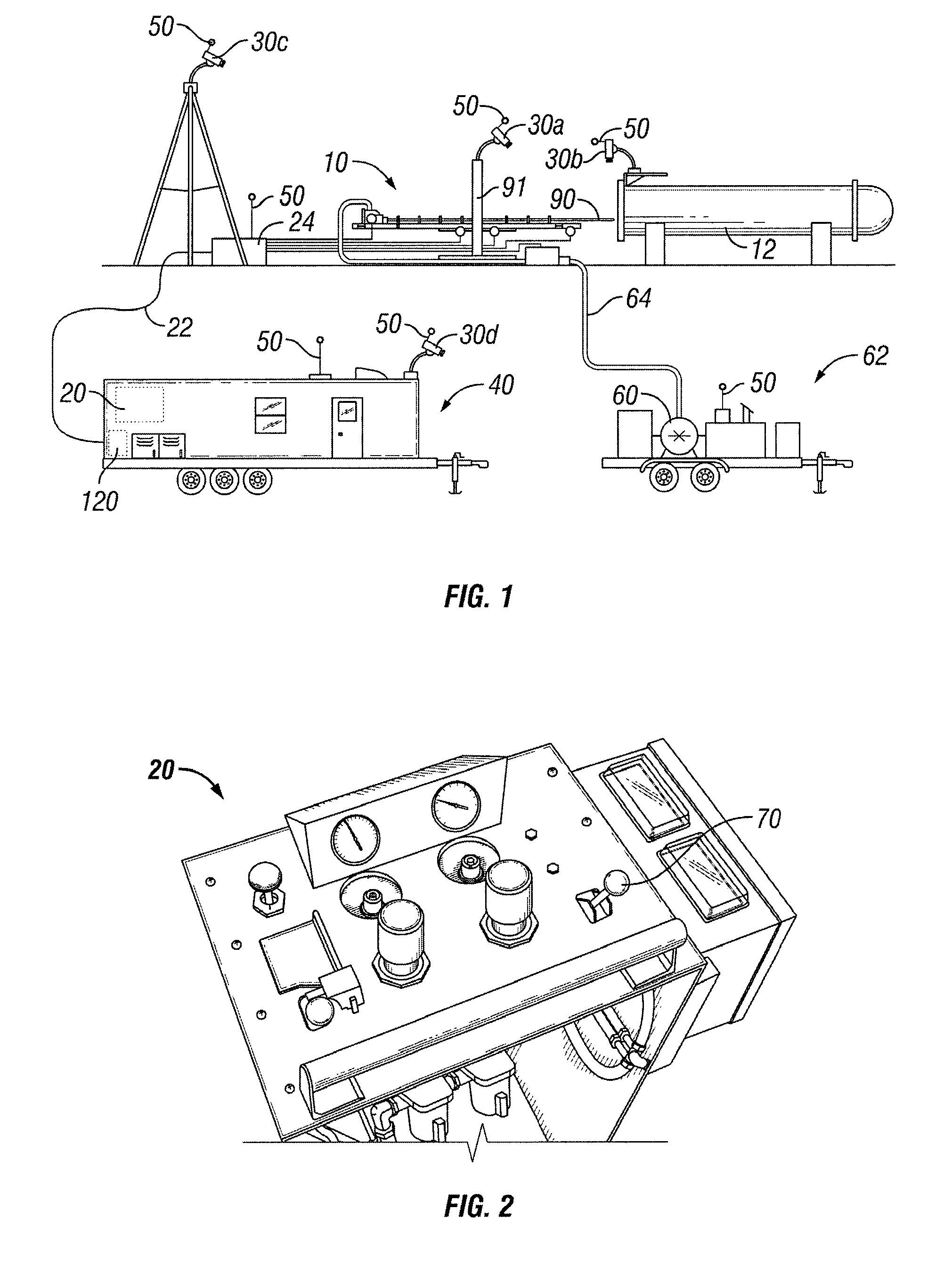
[0044]Operations of assembly 10 can be controlled by a control console 20, as illustrated in FIG. 2. In an illustrative embodiment, control console 20 is remotely located from assembly 10. For example, referring back to FIG. 1, control console 20 can communicate with assembly 10 via ...


PUM


Abstract

An automated heat exchanger tube cleaning assembly and system are provided. The present system can automatically (without ongoing human intervention) survey the tube sheet of a heat exchanger in three-dimensions, convert and record the survey results as a digital file in three-dimensions, and then, according to sequential parameters input via custom software, automatically coordinate via computer one or more cleaning devices to effect the cleaning of each desired tube of the heat exchanger.

Description

RELATED APPLICATIONS[0001]This application claims the benefit, and priority benefit, of U.S. Provisional Patent Application Ser. No. 61 / 070,073, filed Mar. 20, 2008, titled “Automated Heat Exchanger Tube Cleaning Assembly and System.”BACKGROUND[0002]1. Field of Invention[0003]This invention relates generally to the cleaning of heat exchangers, and more particularly, to an apparatus and system for removing residue which accumulates over time in heat exchangers and other tubing and piping used in industrial facilities.[0004]2. Description of the Related Art[0005]Heat exchangers are commonly used in industrial facilities. Over time, these heat exchangers tend to develop residue on the surfaces of the tubes, tube sheets, tube support plates and other internal structural parts. The residue can comprise adherent films, scales, sludge deposits, corrosion and / or other similar materials. Over time, this residue can have an adverse affect on the operational performance of the exchangers. The ...

Claims


Application Information

Patent Timeline
Patent Type & Authority Applications(United States)
IPC IPC(8): B08B9/027G05D1/00
CPCB08B9/04B08B9/0433F28G15/08F28G3/163F28G15/02F28G1/163F28G15/003
Inventor GARDNER, JOHN E.AMADOR, PEDRO E.HOWARD, WILLIAM STAMPSSTONER, JAMES A.
Owner HYDROCHEM
Why Eureka
Try Eureka