Laser machining system with protective enclosure

a technology of laser machining and protective enclosure, which is applied in the direction of laser beam welding apparatus, mechanical equipment, engineering safety devices, etc., can solve the problems of inconvenient use, large space, and inconvenient protection hood, so as to prevent a faulty orientation of laser beam

Inactive Publication Date: 2009-10-15
JENOPTIK AUTOMATISIERUNGSTECHN
View PDF3 Cites 8 Cited by
  • Summary
  • Abstract
  • Description
  • Claims
  • Application Information

AI Technical Summary

Benefits of technology

[0022]Although a limitation of the freedom of movement by an appropriate mechanical design, as offered by the second embodiment, effectively prevents a faulty orientation of the laser beam to the greatest possible extent, it can also lead to mechanical damage, especially to the laser head, and should therefore be used only as a last resort to overcome the safety hurdle.

Problems solved by technology

Especially in the last-mentioned embodiment, there is always the risk that, due to faulty robot control, the laser beam is not directed onto the workpiece as intended.
A laser protection cabin that completely encloses all functional units required for the laser machining system is not only expensive in terms of the material needed and requires considerable space, it also entails a large exhaust volume in conformity with the enclosed inside space.
However, such a protective hood, which is rigidly affixed to the laser head, is not suitable if the laser head on a robot arm is moved in three dimensions in space in order to describe an intended path of motion.
The system disclosed in this document is unsuitable for machining motions that deviate from a straight-line motion or for workpieces on which the protective hood cannot be placed so that it rests flat thereon.

Method used


Image

  • Laser machining system with protective enclosure
  • Laser machining system with protective enclosure
  • Laser machining system with protective enclosure

Examples


Embodiment Construction

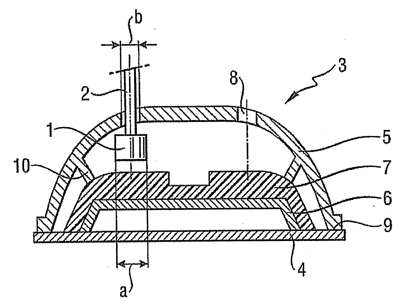
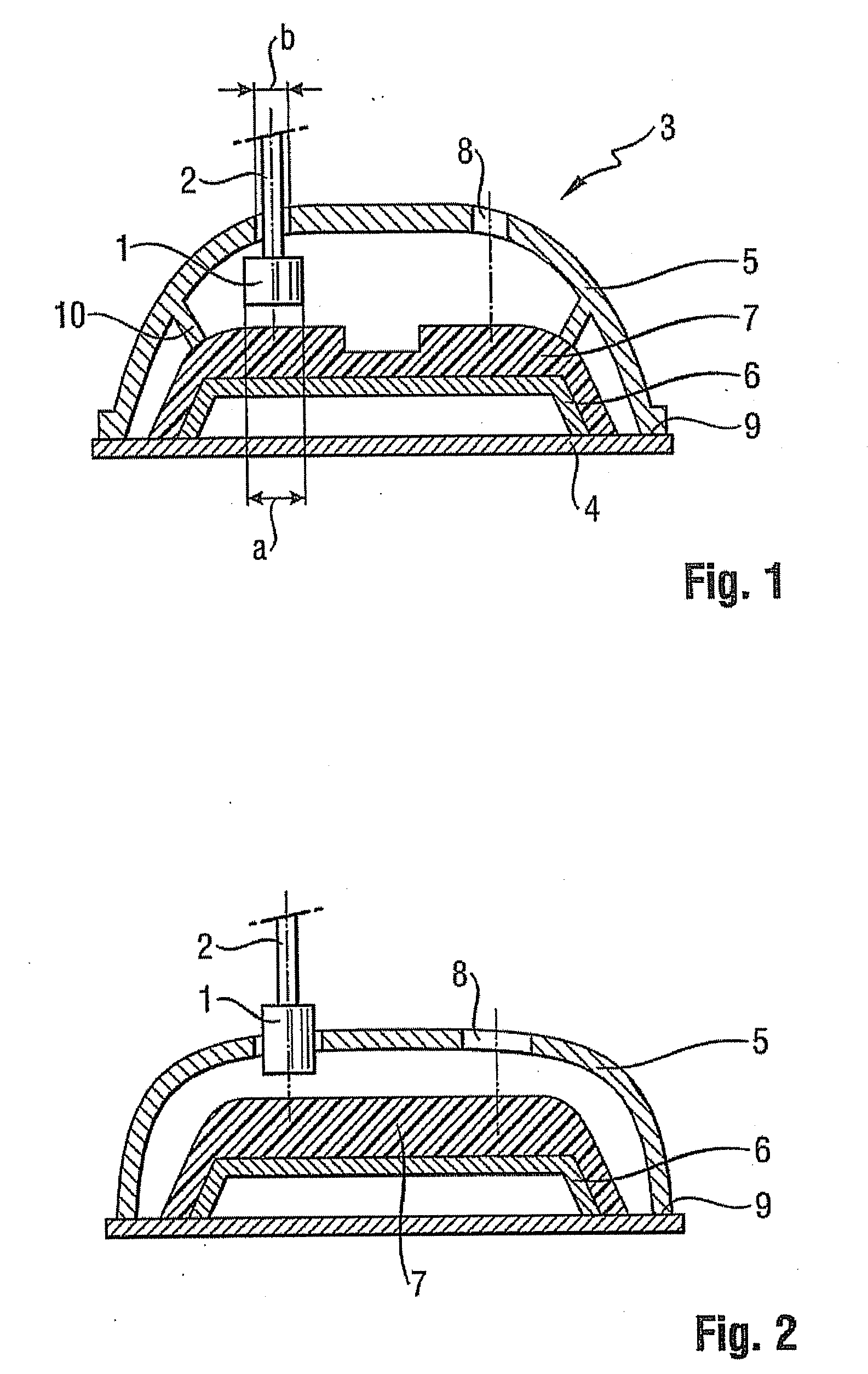
[0042]FIG. 1 shows a section through a useful embodiment of a laser machining system. It basically comprises a laser radiation source (not shown), a robot of which only the end of the robot arm 2 is seen and to which a laser head 1 is attached, a system carrier 4 and a protective hood 5.

[0043]The system carrier 4 and the protective hood 5 are joined along edge 9 and, except for the slit-like openings 8 in the protective hood 5, thus form a closed protective enclosure 3. Mounted on the system carrier 4 is a mounting device 6 on which a workpiece 7 is mounted. The protective hood 5 is preferably fitted with hold-down devices 10 which affix the workpiece 7 to the mounting device 6.

[0044]As FIG. 1 illustrates, the protective hood 5 in combination with the system carrier 4 completely encloses the workpiece 7 in such a manner that the free volume under the protective cover 5 is small, yet the laser head 1 can move entirely inside the protective hood 5 under the openings 8 at a predetermin...


PUM

PropertyMeasurementUnit
lengthaaaaaaaaaa
heightaaaaaaaaaa
volumeaaaaaaaaaa

Abstract

The present invention relates to a laser machining system with a protective enclosure wherein the protective enclosure is basically formed by a protective hood which encloses a workpiece that is mounted on a mounting device in such a manner that a laser head can be moved within the protective hood through the slit-shaped opening by means of a robot arm.

Description

FIELD OF THE INVENTION[0001]The present invention relates generally to laser machining systems and more particularly to a laser machining system with a protective enclosure in which the protective enclosure is formed by a protective hood which encloses a workpiece mounted on a mounting device in such a manner that a laser head can be moved by means of a robot arm.BACKGROUND OF THE INVENTION[0002]In addition to the functional units that are vital to the operation of laser machining systems, such as a laser beam source, means for delivering the laser beam to the site to be machined and a device for mounting a workpiece that is to be machined, such laser machining systems generally also comprise means for discharging waste gases that are generated in the course of the laser machining process as well as means for protecting (protective enclosure) the operating personnel from laser radiation.[0003]The relative movement between the laser beam as the tool and the workpiece, which movement ...

Claims


Application Information

Patent Timeline
Patent Type & Authority Applications(United States)
IPC IPC(8): B23K26/38
CPCF16P1/06B23K26/427B23K26/706
Inventor FEISTEL, ULF
Owner JENOPTIK AUTOMATISIERUNGSTECHN
Why Eureka
Try Eureka