Simple PC-level dual-power change-over switch control circuit

A switch control circuit, dual power switching technology, applied in circuit devices, emergency power supply arrangements, emergency protection circuit devices for limiting overcurrent/overvoltage, etc. The circuit is complex and other problems, to achieve the effect of simple structure, less circuit components, and simple overall structure

Pending Publication Date: 2020-04-14
DELIXI ELECTRIC
View PDF1 Cites 1 Cited by
  • Summary
  • Abstract
  • Description
  • Claims
  • Application Information

AI Technical Summary

Problems solved by technology

[0006] First, both the signal and power in the circuit use a resistance-capacitance step-down circuit to take power from the phase line, and the capacitor is large, which will increase the size of the PCB;
[0007] The second is that the circuit realizes the function through three relays, the control circuit is complicated, and it is difficult to realize the miniaturization and simplification

Method used


Image

  • Simple PC-level dual-power change-over switch control circuit
  • Simple PC-level dual-power change-over switch control circuit
  • Simple PC-level dual-power change-over switch control circuit

Examples


Embodiment Construction

[0038] The present invention will be described in detail below in conjunction with the accompanying drawings and specific embodiments. This embodiment is carried out on the premise of the technical solution of the present invention, and detailed implementation and specific operation process are given, but the protection scope of the present invention is not limited to the following embodiments.

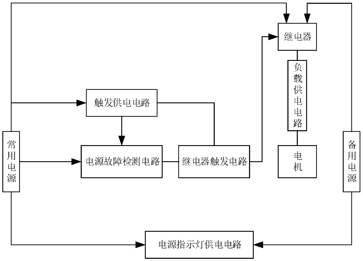
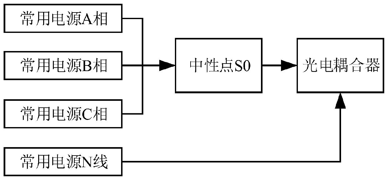
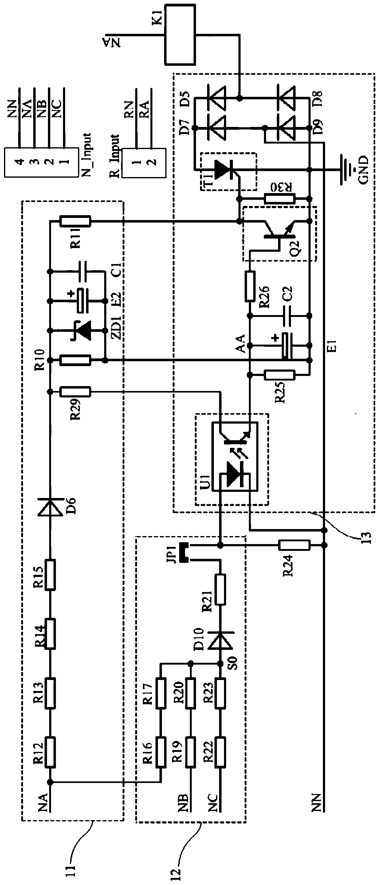
[0039] A simple PC-level dual power switch control circuit, such as figure 1 , for accessing the load M 1 When the three-phase four-wire common power supply fails, it will automatically switch to the backup power supply including A line and N line. The PC-level dual power switch control circuit includes a relay drive circuit, a load power supply circuit and a relay K 1 , the relay drive circuit includes a trigger power supply circuit 11, a power failure detection circuit 12 and a relay trigger circuit 13, such as figure 2 with image 3 , the power failure detection circuit 12 in...


PUM


Abstract

The invention relates to a simple PC-level dual-power change-over switch control circuit. The circuit comprises a relay drive circuit, a load power supply circuit and a relay K1. The relay drive circuit comprises a power supply fault detection circuit, a trigger power supply circuit and a relay trigger circuit. A normally open contact and a normally closed contact of a conversion contact of the K1are correspondingly connected with a frequently-used power supply and a standby power supply, and a common end is connected to the M1 through a load power supply circuit. The power supply fault detection circuit comprises three voltage reduction circuits connected with three phases of a common power supply. The relay trigger circuit comprises an optical coupler U1, a triode Q2 and a silicon controlled rectifier T1. Wherein the neutral point is connected with the input end of the U1, the output end of the trigger power supply circuit is respectively connected with the C pole of the U1, the C pole of the Q2 and the gate pole of the T1, the E pole of the U1 is connected with the B pole of the Q2, and the frequently-used power supply, the K1, the T1 and the ground wire are sequentially connected to form a loop. Compared with the prior art, the control circuit has the advantages of small size, low cost and the like.

Description

technical field [0001] The invention relates to the field of dual power switch electrical appliances, in particular to a simple PC-level dual power switch control circuit. Background technique [0002] In order to prevent long-term power outages in some occasions that require continuous power supply, the current method is usually to use two power supplies, one common power supply and one backup power supply, and switch to the backup power supply when the common power supply fails, among which automatic switching appliances are commonly used The device for power switching, Automatic transfer switching equipment (ATSE) for short, is a switching device that ensures continuous and reliable power supply for important loads, so the quality and rational use of ATSE products are particularly important. The automatic switch consists of three parts: switch body, transmission mechanism and controller. Commonly used switch bodies include contactors, circuit breakers and load disconnect...

Claims


Application Information

Patent Timeline
Patent Type & Authority Applications(China)
IPC IPC(8): H02J9/06H02H7/09H02H9/02
CPCH02H7/09H02H9/02H02J9/066Y02B70/30Y04S20/20
Inventor 李建模陈琦琪
Owner DELIXI ELECTRIC
Why Eureka
Try Eureka