Piezoelectric vibrating devices and methods for manufacturing same

a technology of vibrating device and piezoelectric, which is applied in the direction of piezoelectric/electrostrictive transducers, generators/motors, transducer types, etc., can solve the problems of excessive increase or fluctuation of ci value, increase the dependency characteristics of the drive level of the device, and increase the stress of the adhesive hardening, so as to reduce the stress and reduce the unwanted vibration frequency , the effect of stable vibration frequency

Inactive Publication Date: 2009-10-15
NIHON DEMPA KOGYO CO LTD
View PDF1 Cites 25 Cited by
  • Summary
  • Abstract
  • Description
  • Claims
  • Application Information

AI Technical Summary

Benefits of technology

[0014]In a piezoelectric device according to a sixth embodiment, the first connection electrode and the third connection electrode are at least 10% of the longitudinal length of the piezoelectric device away from each other in the longitudinal direction of the supporting member. With such a configuration, the effects of stress imparted by hardening of the adhesive can be reduced. Reducing stress reduces unwanted changes of vibration frequency after adhesive bonding, allowing piezoelectric devices to be manufactured having stable vibration frequencies.
[0015]Piezoelectric vibrating devices according to various embodiments exhibit less reduction of their CI values as they are miniaturized. This allows the piezoelectric devices to meet performance demands of miniaturization.

Problems solved by technology

Stress can also increase or cause fluctuation in the CI value and increase the dependency characteristics of the drive level of the device.
Use of a supporting member with increasingly miniaturized devices may allow applied electrically conductive adhesive to spread out excessively, which can prevent the DLD (Drive Level Dependency) of the device from being reduced sufficiently and can cause an excessive increase or fluctuation in CI value.

Method used


Image

  • Piezoelectric vibrating devices and methods for manufacturing same
  • Piezoelectric vibrating devices and methods for manufacturing same
  • Piezoelectric vibrating devices and methods for manufacturing same

Examples


first embodiment

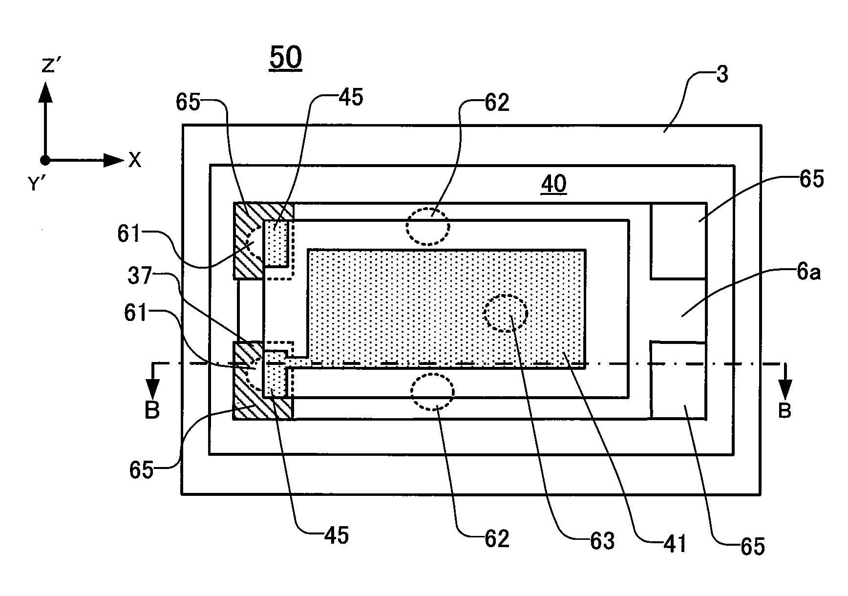
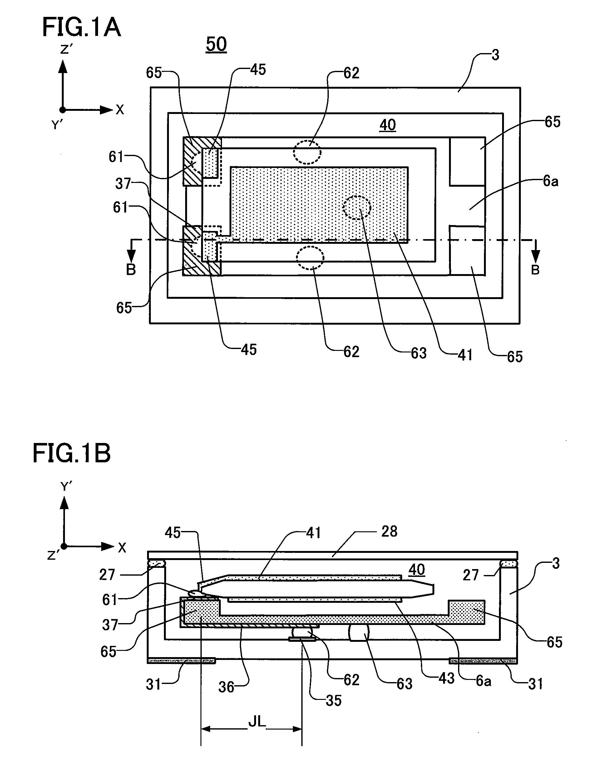
[0033]FIG. 1A depicts a piezoelectric vibrating device 50 of the first embodiment. FIG. 1B is a cross-sectional view taken along the line B-B in FIG. 1A. As shown in FIGS. 1A and 1B, the piezoelectric vibrating device 50 comprises an AT-cut crystal vibrating piece 40, a base 3 holding the piece 40, a lid 20 for air-tight sealing, and a supporting member 6a. In the piezoelectric device 50 the AT-cut crystal vibrating piece 40 is situated in a space formed by the base 3 and lid 28.

[0034]With respect to quartz crystal, the “AT-cut” is one in which the main surface (YZ surface) is tilted 35° 15′ in the Y-axis direction from the Z-axis to the Y-axis of the crystal axes (XYZ). Hereinbelow, whenever the axial direction of an AT-cut crystal vibrating piece is described, the generally-tilted new axes are denoted the Y′ axis and the Z′ axis.

[0035]As FIGS. 1A and 1B show, on the both edges in X direction of the AT-cut crystal vibrating piece 40, the edges are processed, such as by beveling or ...

second embodiment

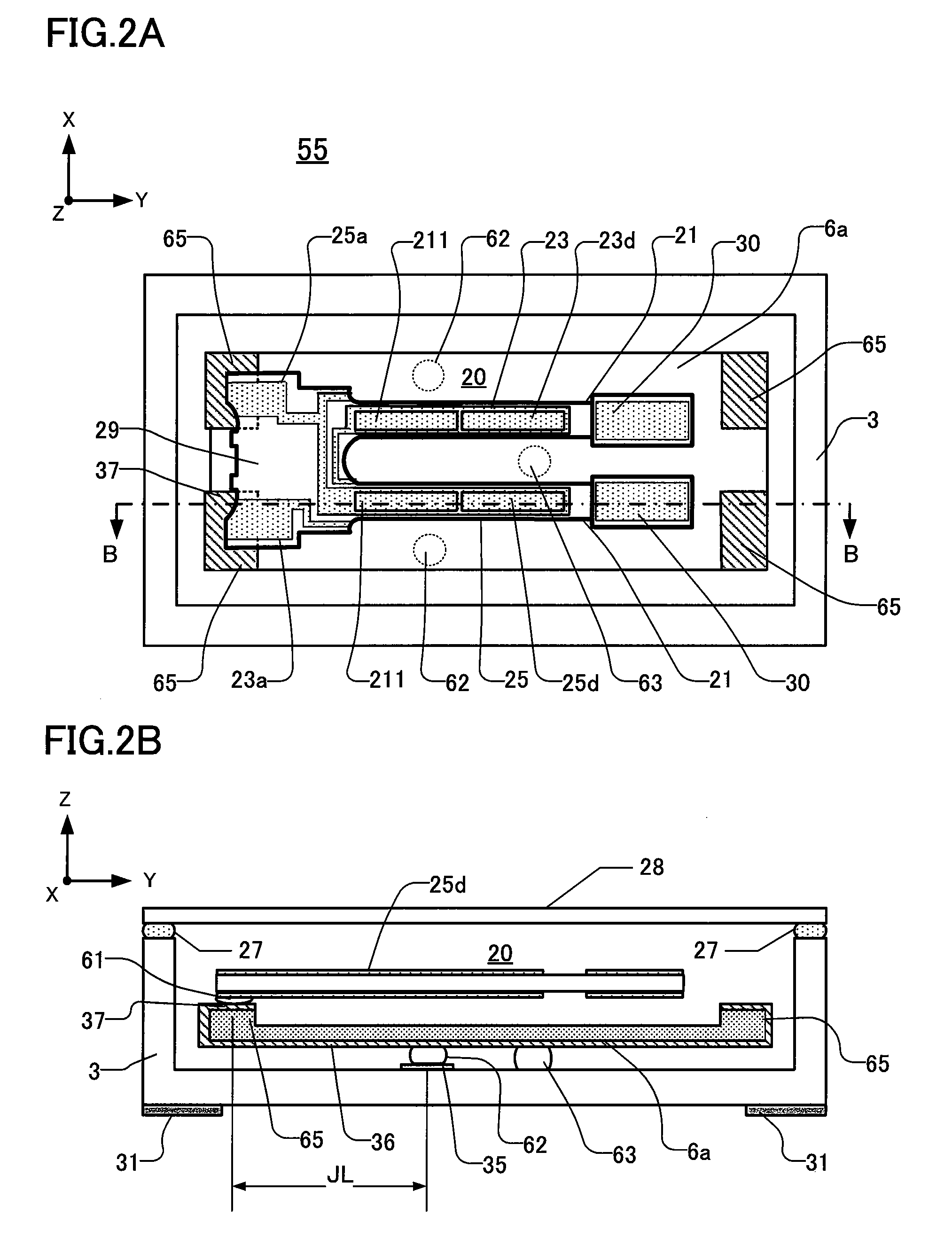
[0044]A piezoelectric vibrating device 55 of this embodiment is shown in FIGS. 2A and 2B. FIG. 2A shows the device 55 with the lid 28 removed. FIG.2B is a cross-sectional view taken along the line B-B line in FIG. 2A. In the second embodiment, components having the same respective reference numerals as corresponding components in the first embodiment have the same respective functions and configurations.

[0045]The piezoelectric vibrating device 55 comprises a tuning-fork type crystal vibrating piece 20, a base 3 holding the piece 20, a lid 28 for air-tight sealing, and a supporting member 6a. The tuning-fork type crystal vibrating piece 20 is situated in a space defined by the base 3 and lid 28. The tuning-fork type crystal vibrating piece 20 oscillates at a frequency of, for example, 32.768 kHz. Not intending to be limiting, the piece 20 has the following exemplary dimensions: Y-direction length about 1.45 mm, X-direction about 0.5 mm, and Z-direction height about 0.1 mm.

[0046]The t...


PUM

PropertyMeasurementUnit
heightaaaaaaaaaa
heightaaaaaaaaaa
lengthaaaaaaaaaa

Abstract

An exemplary piezoelectric device includes a base having a first connection electrode electrically connected to an external electrode. A second connection electrode is connected to the first connection electrode on a first main surface of a supporting member affixed to the base. A third connection electrode, formed on a second main surface of the supporting member, is electrically connected to the second connection electrode. A piezoelectric vibrating piece is affixed to the supporting member by application of an adhesive applied to the third connection electrode. The piezoelectric vibrating piece and includes excitation electrodes. A convexity is located and extends in a designated direction relative to the third connection electrode to prevent applied adhesive from spreading beyond a designated area of the piezoelectric vibrating piece.

Description

CROSS-REFERENCE TO RELATED APPLICATION [0001]This application claims priority to and the benefit of Japan Patent Application No. 2008-102256, filed on Apr. 10, 2008, in the Japan Patent Office, the disclosure of which is incorporated herein by reference in its entirety.FIELD [0002]This disclosure pertains, inter alia, to piezoelectric vibrating devices comprising supporting members made using piezoelectric substrates, and to methods for manufacturing same.DESCRIPTION OF THE RELATED ART [0003]Various types of clocks, home electric appliances, and consumer electronics, and various types of commercial / industrial electrical apparatus such as information / communication devices and Office-Automation devices utilize at least one oscillator. These oscillators typically are manufactured by packaging a piezoelectric resonator, a piezoelectric vibrating piece, or an IC chip as a clock source for addition to and use by an electronic circuit of the apparatus. In other apparatus, piezoelectric tim...

Claims


Application Information

Patent Timeline
Patent Type & Authority Applications(United States)
IPC IPC(8): H01L41/053H01L41/047H01L41/22H03H9/05H03H9/10
CPCH03H9/0519Y10T29/42H03H9/21H03H9/1021
Inventor NISHIMURA, YUYASUGIYAMA, TOSHIO
Owner NIHON DEMPA KOGYO CO LTD
Why Eureka
Try Eureka