3D poly-phase transformer

Inactive Publication Date: 2009-10-15
CODY TRANSFORMER
View PDF18 Cites 13 Cited by
  • Summary
  • Abstract
  • Description
  • Claims
  • Application Information

AI Technical Summary

Benefits of technology

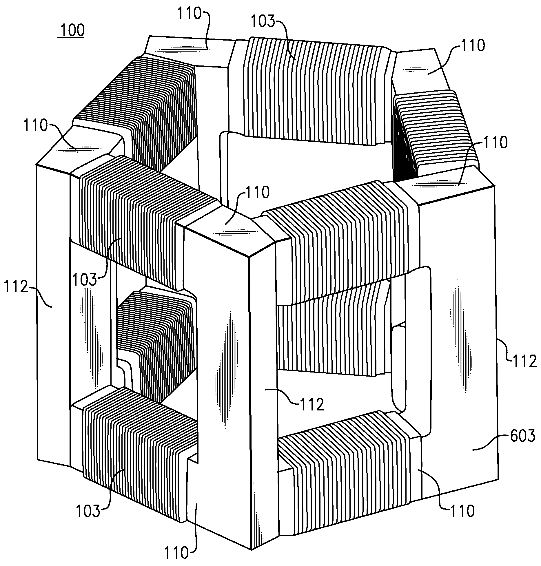
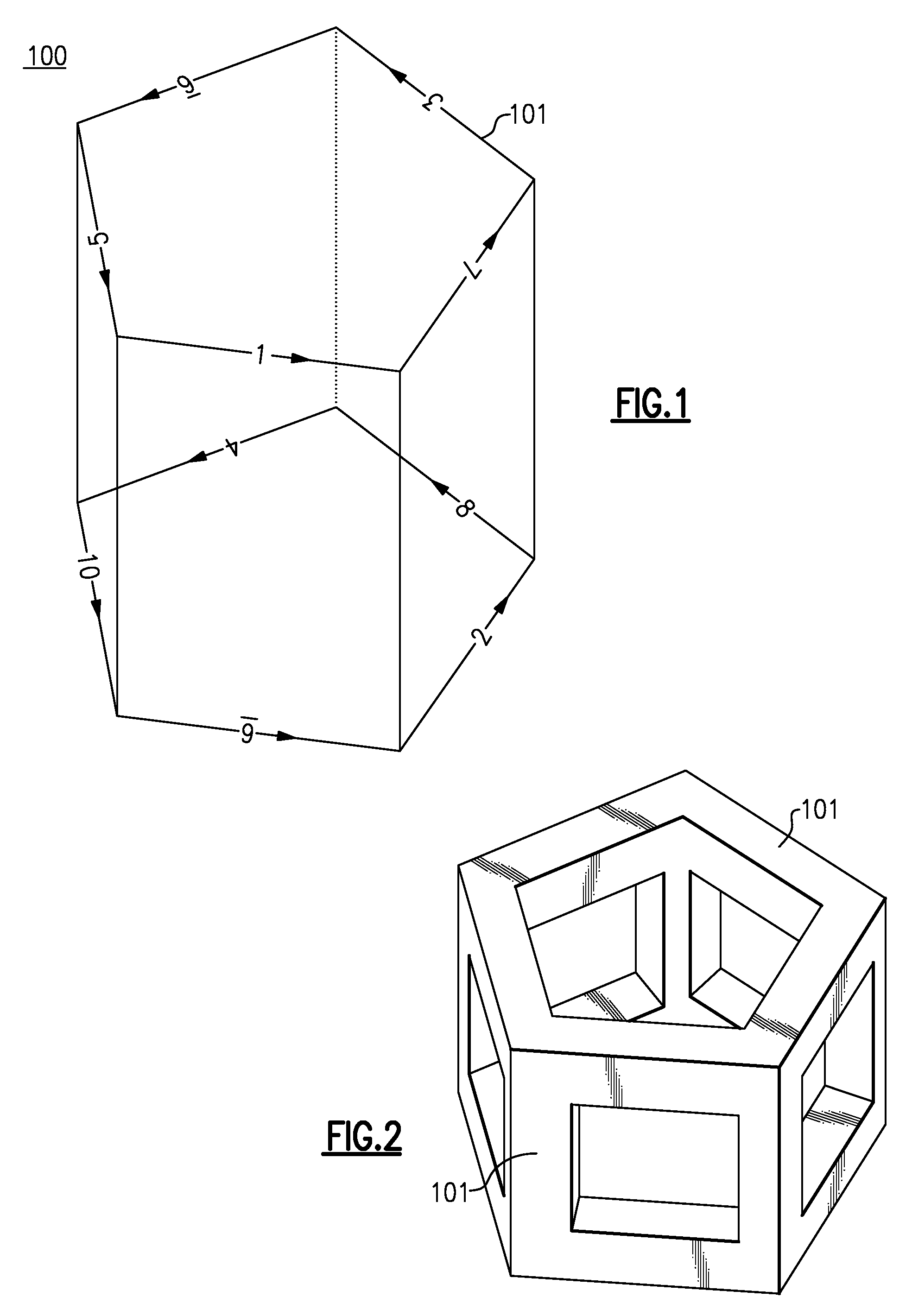
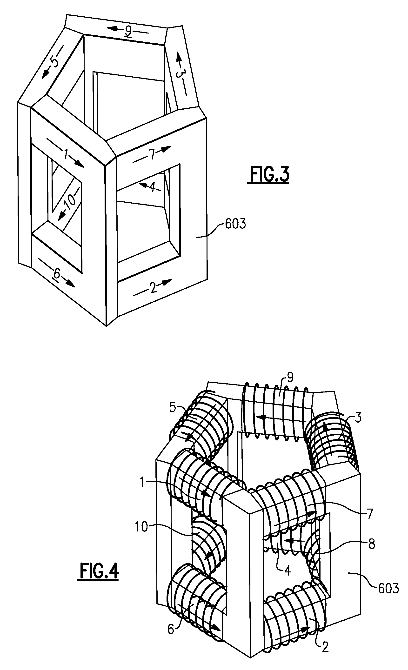
[0032]In yet another embodiment, the 3D poly-phase transformer includes three or more base planes,

Problems solved by technology

One problem is that present types of transformers have relatively large physical si

Method used


Image

  • 3D poly-phase transformer
  • 3D poly-phase transformer
  • 3D poly-phase transformer

Examples


example 1

[0114]Mammography, CT, Tomosynthesis, and Dual Energy X-Ray Applications: For mammography applications and in particular for digital mammography, the variation of power needed to be delivered to an x-ray tube is typically between about 2 kW and 15 kW. For the reasons discussed above, it is desirable that there be a relatively low ripple level across the full dynamic range of the delivered power. Currently, typical ripple levels are in the range of 3% to 4%. Using the inventive poly-phase 3D transformer in a poly-phase power supply, it is believed that about 1% ripple voltage can be achieved. Digital mammography also demands very short kilovolt power supply “rise” and “fall” times. Generally, rise and fall times (power supply on-off times) of more than 1 msec negatively impact the digital detector performance and patient throughput (efficiency of the x-ray process as measured, for example, by the imaging time needed per patient). On / off switching times are particularly relevant in du...

example 2

[0120]Testing of poly-phase power supply configurations was performed in the laboratory using poly-phase transformers. FIG. 17 shows an oscilloscope screen capture (oscillogram) of a kilovolt high voltage (HV) pulse produced using a two phase configuration. The HV pulse can be seen displayed on a horizontal scale of 20 μs / division and with a vertical scale of 600 V / division. The ripple at the flat top is perceptible. The smaller regular pulses of the lower trace represent the AC drive voltage. FIG. 18 shows a view of the oscillogram of FIG. 17 magnified in time (2 μs / division). The oscillogram of FIG. 19 shows a HV pulse generated using three phases. The flat top ripple can be seen to be improved over the two phase example, yet the ripple is still noticeable. FIG. 20 shows a magnified view of the oscillogram of FIG. 19. The oscillogram of FIG. 21 shows a HV pulse generated using four phases. The flat top ripple can be seen to be improved over the three phase example, yet again the r...


PUM

PropertyMeasurementUnit
Poweraaaaaaaaaa
Electric potential / voltageaaaaaaaaaa
Mechanical propertiesaaaaaaaaaa

Abstract

A three dimensional (3D) poly-phase transformer includes a plurality of transformer ribs mechanically and magnetically coupled such that each transformer rib forms a leg of a polygon. A plurality of the polygons forms a 3D polyhedron structure. At least two base planes of the 3D poly-phase transformer including a polygon have a plurality of base ribs. At least four side ribs of the 3D poly-phase transformer are disposed between the base planes. The 3D poly-phase transformer includes a plurality of primary and secondary transformer windings. Another 3D poly-phase transformer includes at least two base planes having a closed curve. Each closed curve includes a plurality of curved base ribs, and at least four side ribs of the 3D poly-phase transformer disposed between the base planes. Methods of manufacturing three dimensional (3D) poly-phase transformers are also described.

Description

CROSS-REFERENCE TO RELATED APPLICATIONS[0001]This application claims priority to and the benefit of co-pending U.S. provisional patent application Ser. No. 61 / 044,770, filed Apr. 14, 2008 entitled “3D POLY-PHASE TRANSFORMER”, incorporated herein by reference in its entirety.FIELD OF THE INVENTION[0002]This invention relates generally to a poly-phase transformer and more particularly to a three dimensional poly-phase transformer.BACKGROUND OF THE INVENTION[0003]Electrical transformers are used to transfer and transform alternating current, typically from at least one primary winding to at least one secondary winding. The transformation aspect includes the ability of a transformer to create a higher or lower output voltage at the output of a secondary winding as compared to the input voltage at a primary winding. The fundamental principle behind energy transfer across a transformer is that an AC current in one or more primary windings creates a magnetic flux in a transformer core typi...

Claims


Application Information

Patent Timeline
IPC IPC(8): H05G1/10H01F30/12H01F41/00
CPCH01F27/24H01F27/263Y10T29/49073H01F30/12H01F27/306H05G1/10
Inventor KHUTORYANSKY, OSCARROSEVEAR, THOMAS WILLIAM
Owner CODY TRANSFORMER
Why Eureka
Try Eureka