
Developing apparatus and electrophotographic image-forming apparatus

Inactive Publication Date: 2009-10-15
CANON KK
View PDF2 Cites 7 Cited by
  • Summary
  • Abstract
  • Description
  • Claims
  • Application Information

AI Technical Summary

Benefits of technology

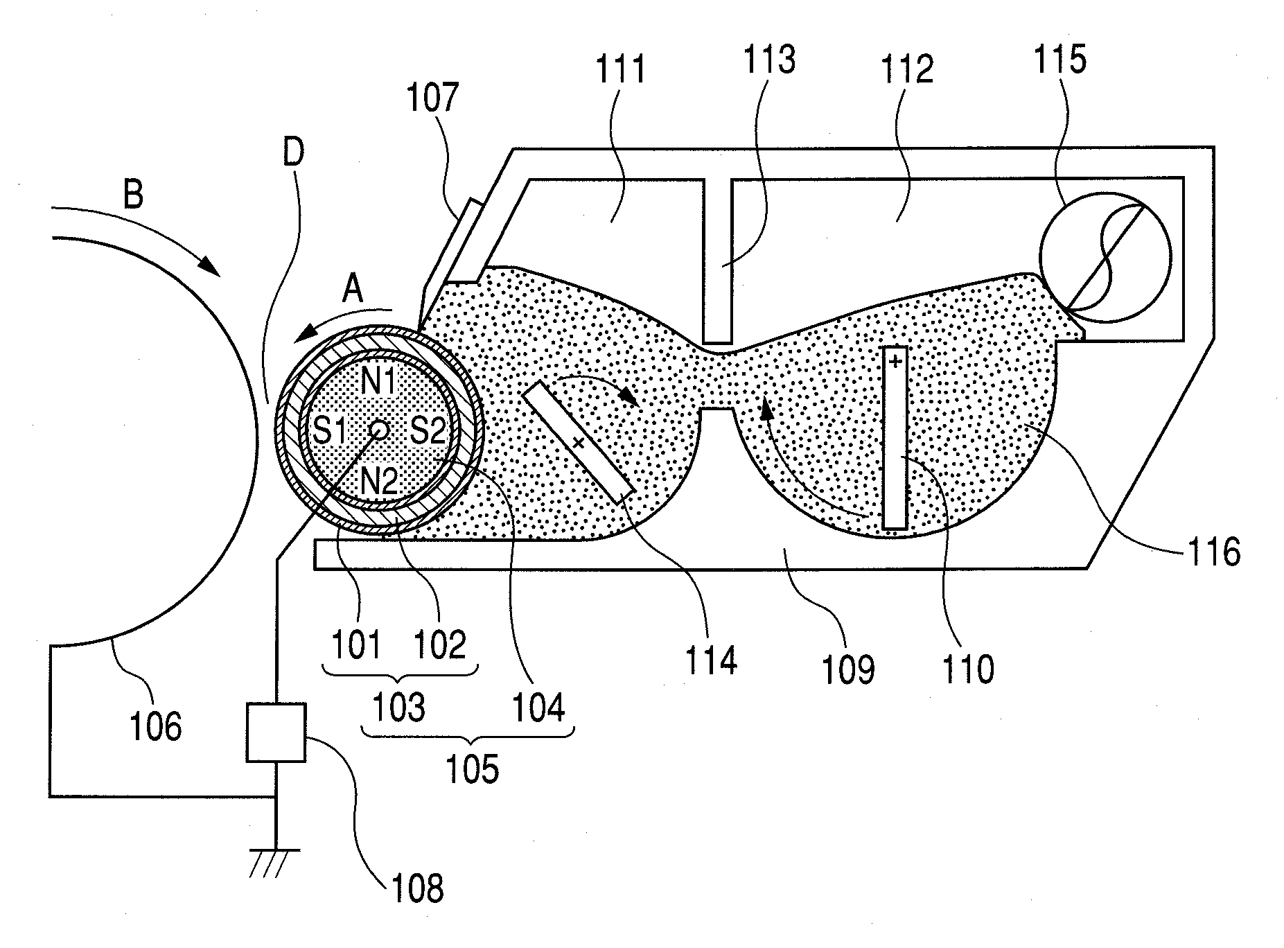
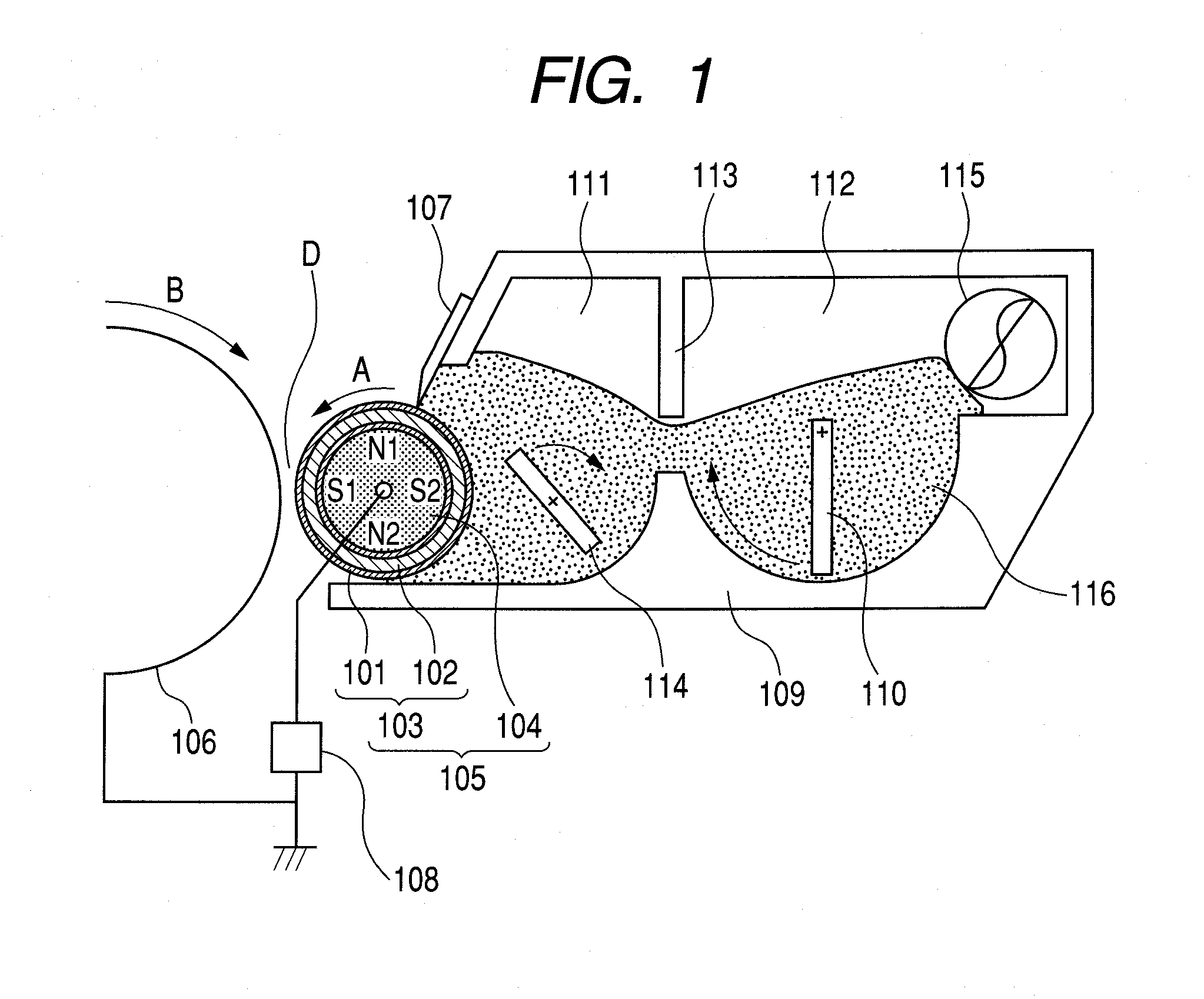
[0011]The inventors of the present invention have made investigation into the above-mentioned increase of image density occurring after a pause. As a result, the inventors have found the correlation between the increase and the charge-up of a developer. That is, the inventors have considered as follows: mirror force affecting the developer which has undergone charge-up owing to extensive operation is weakened by setting a pause period, and an image can be easily developed with the developer at the time of printing after a pause, whereby an image density increases.
[0015]As described above, according to the present invention, a fluctuation in image density can be suppressed even in a discontinuous printing mode provided with a pause period.

Problems solved by technology

However, when the amount of a magnetic material is reduced and the particle size of a developer is reduced, a so-called charge-up phenomenon as described below is apt to occur: the developer is brought into a passive state by mirror image force with the surface of a developing sleeve, so a latent image on a photosensitive drum is difficult to develop with the developer from the developing sleeve.

Method used


Image

  • Developing apparatus and electrophotographic image-forming apparatus
  • Developing apparatus and electrophotographic image-forming apparatus
  • Developing apparatus and electrophotographic image-forming apparatus

Examples


example 1

[0320]

[0321]A developer bearing member g-1 to be combined with the developer c-1 prepared in advance was produced by the following method. First, the following materials were mixed, and the mixture was treated with a horizontal sand mill (filled with glass beads having a diameter of 0.6 mm in the packing ratio of 85%), whereby a primary dispersion liquid h-1 was obtained.

Binder resin l-1166.7 parts by mass(solid content 100 parts by mass)Graphitized particles b-1  90 parts by massCarbon black  10 parts by massMethanol133.3 parts by mass

[0322]Next, the following materials were mixed, and the mixture was treated with a vertical sand mill (filled with glass beads having a diameter of 0.8 mm in the packing ratio of 50%), whereby a secondary dispersion liquid i-1 was obtained. Further, the dispersion liquid was diluted with methanol, whereby a coating liquid j-1 having a solid content of 37% was obtained.

Primary dispersion liquid h-1400 parts by mass(solid content 200 parts by mass)Binde...

examples 2 to 8

[0337]A developer to be combined with the above developer bearing member g-1 was changed as shown in Table 6. Table 6 shows various numerical values representing the surface shape of the developer bearing member g-1 in relation to each developer. In addition, image evaluation was performed in the same manner as in Example 1 except that an electrophotographic image-forming apparatus according to each combination was used. Table 7 shows the results.

example 9

[0338]A developer bearing member g-2 to be combined with the developer c-1 was produced as described below. In other words, the developer bearing member g-2 was produced in the same manner as in the developer bearing member g-1 except that the graphitized particles d-1 used in the production of the above-mentioned developer bearing member g-1 were changed to the graphitized particles d-2. Table 6 shows various numerical values representing the surface shape of the developer bearing member g-2 in relation to the developer c-1. In addition, image evaluation was performed in the same manner as in Example 1 except that an electrophotographic image-forming apparatus in which the developer c-1 and the developer bearing member g-2 were combined with each other was used. Table 7 shows the results.


PUM


Abstract

A developing apparatus is provided which can suppress a fluctuation in image density in a discontinuous printing mode provided with a pause period. The developing apparatus includes a developer for developing an electrostatic latent image on a photosensitive drum, a developer bearing member for carrying and conveying the developer and a developer layer thickness-regulating unit placed close to the developer bearing member for regulating the amount of the developer carried and conveyed by the developer bearing member, the developer layer thickness-regulating unit being. As the developer, a negatively chargeable, one-component, magnetic toner is used having magnetic toner particles containing a binder resin and a magnetic iron oxide particle, and has a specific saturation magnetization, specific weight-average particle diameter and specific composition. The developer bearing member includes a surface layer containing a binder resin, a quaternary ammonium salt, graphitized particles, and conductive, spherical resin particles, and has a specific surface shape.

Description

[0001]This application is a continuation of International Application No. PCT / JP2009 / 052254, filed on Feb. 4, 2009, which claims the benefit of Japanese Patent Application No. 2008-037419 filed on Feb. 19, 2008.BACKGROUND OF THE INVENTION[0002]1. Field of the Invention[0003]The present invention relates to a developing apparatus to be used for developing an electrostatic latent image formed on an electrostatic latent image-bearing member such as a photosensitive member or an electrostatic recording derivative, and an electrophotographic image-forming apparatus including the developing apparatus.[0004]2. Description of the Related Art[0005]Electrophotography generally involves the utilization of a photoconductive substance, and includes: forming an electrostatic latent image on an electrostatic latent image-bearing member (photosensitive drum) by various means; applying a developing bias to a developing zone; developing the electrostatic latent image with a developer to form a toner ...

Claims


Application Information

Patent Timeline
IPC IPC(8): G03G15/09
CPCG03G9/0833G03G2215/0609G03G9/0835
Inventor MATSUDA, TAKUMASHIMAMURA, MASAYOSHIAKASHI, YASUTAKAOTAKE, SATOSHIITO, MINORUWAKABAYASHI, KAZUHITOYOSHIBA, DAISUKE
Owner CANON KK
Learn More