
Gateway with adaptive air interfaces

Inactive Publication Date: 2009-10-15
SONY ERICSSON MOBILE COMM AB
View PDF10 Cites 59 Cited by
  • Summary
  • Abstract
  • Description
  • Claims
  • Application Information

AI Technical Summary

Benefits of technology

[0018]According to one aspect of the invention, a system for minimizing power consumption in portable electronic devices includes: a wireless gateway for providing access to a network, said gateway including a first multi-mode radio circuit; a portable electronic device including a second multi-mode radio circuit, wherein the first and second radio circuits each include a plurality of transceivers, and one transceiver of each of the first and second radio circuits requires less power than respective other transceivers of the first and second radio circuits, and wherein at least one of the gateway or the portable electronic device is operative to a) select a transceiver of the respective plurality of transceivers based on characteristics of a communication request; and b) communicate the selected transceiver to the other of the gateway or the portable electronic device via the respective one transceiver.
[0027]According to one aspect of the invention, a method of minimizing power consumption in a terminal that includes a multi-mode radio circuit having a plurality of different transceivers for communicating over a plurality of different wireless standards, wherein a first transceiver of the plurality of transceivers requires less power than other transceivers of the plurality of transceivers, the method including: selecting a transceiver of the plurality of transceivers based on characteristics of a communication request; and using the first transceiver to communicate the selected transceiver to a receiving device.

Problems solved by technology

A problem with the cellular air interface, however, is that due to limited spectrum opportunities, the air interface may be limited to GSM or EDGE.
While this lower throughput is sufficient for voice communications, it may pose limitations for internet use.
Moreover, WiFi interfaces typically consume significantly more power than that of cellular air interfaces.

Method used


Image

  • Gateway with adaptive air interfaces
  • Gateway with adaptive air interfaces
  • Gateway with adaptive air interfaces

Examples


Embodiment Construction

[0046]Embodiments of the present invention will now be described with reference to the drawings, wherein like reference numerals are used to refer to like elements throughout. It will be understood that the figures are not necessarily to scale.

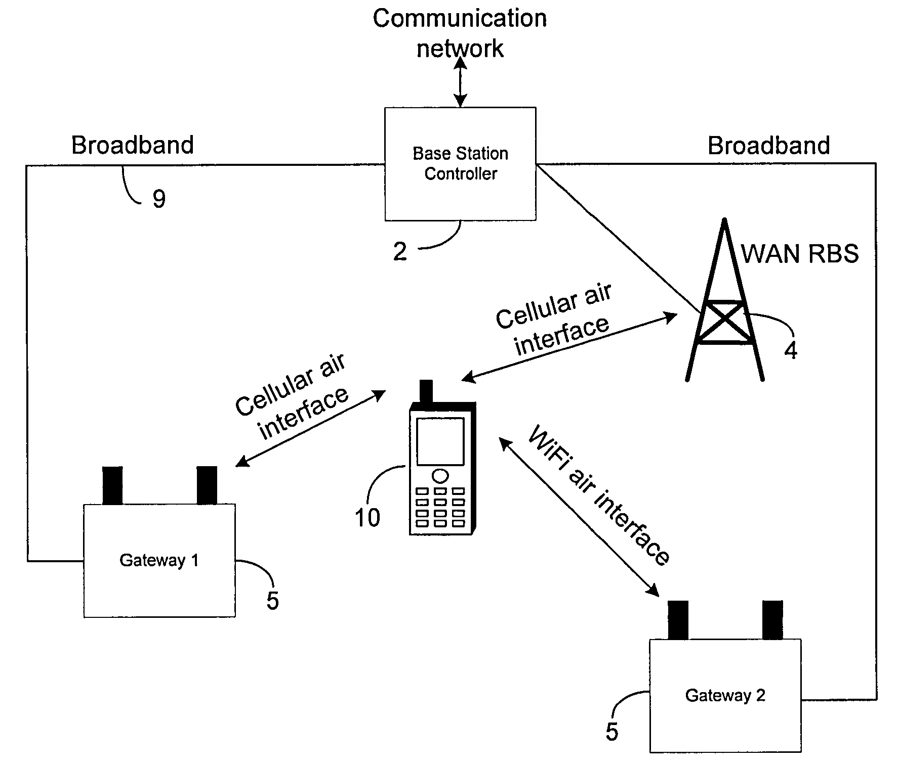
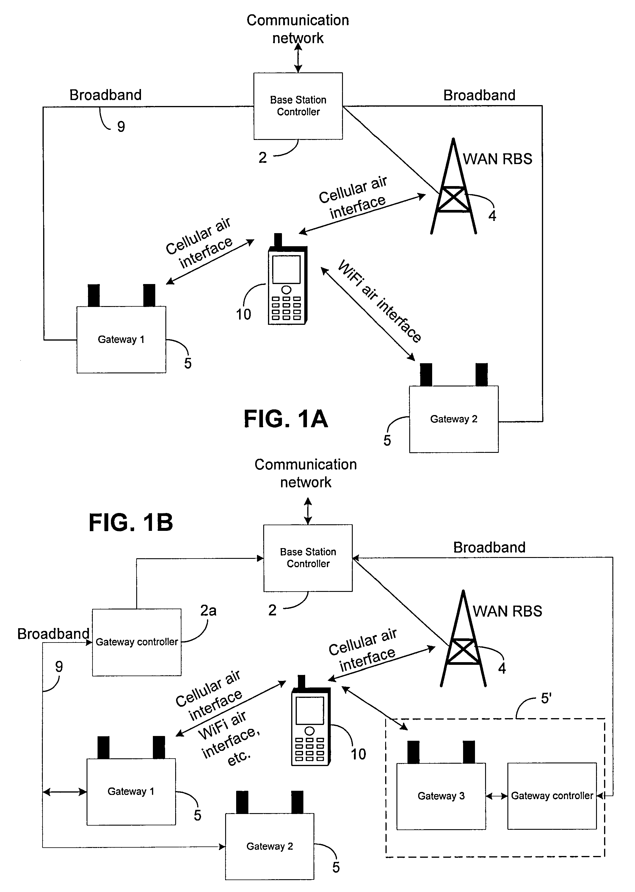
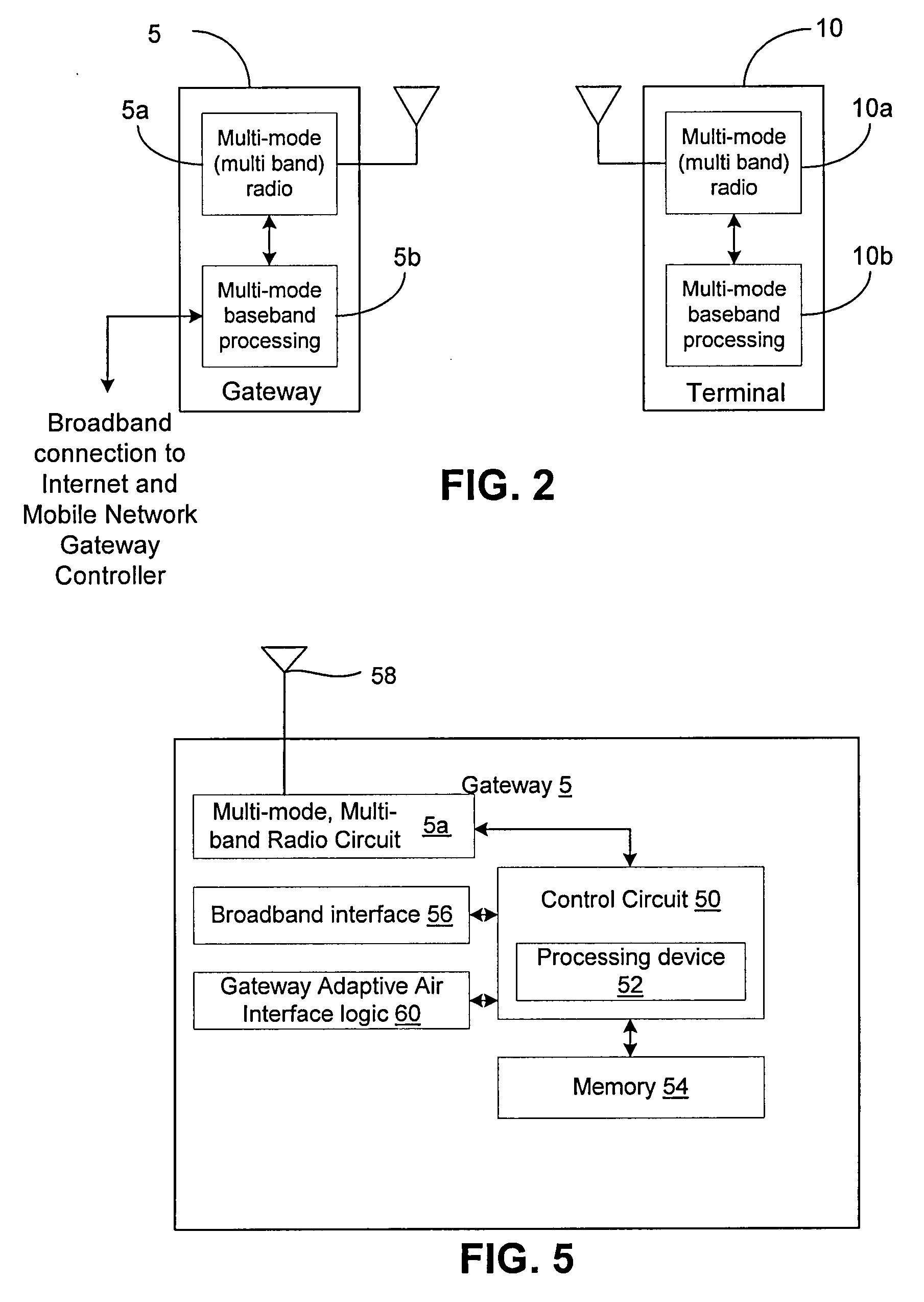
[0047]The interchangeable terms “electronic equipment” and “electronic device” include portable radio communication equipment. The term “portable radio communication equipment,” includes all equipment such as mobile telephones, pagers, communicators, electronic organizers, personal digital assistants (PDAs), smart phones, portable communication apparatus, portable gaming devices, portable media devices (video and / or audio), and the like. The term “gateway” includes all equipment such as femtocells, wireless access points and the like that enable or provide access to a network. The term “terminal” includes electronic devices and gateways as defined above.

[0048]In the present application, embodiments of the invention are described primarily in t...


PUM


Abstract

A wireless terminal includes a multi-mode radio circuit having a plurality of different transceivers for communicating over a plurality of different wireless standards, wherein a first transceiver of the plurality of transceivers requires less power than other transceivers of the plurality of transceivers. The terminal also includes a processor and memory, and logic stored in memory and executable by the processor. The logic includes logic that selects a transceiver of the plurality of transceivers based on characteristics of a communication request, and logic that uses the first transceiver to communicate the selected transceiver to a receiving device.

Description

TECHNICAL FIELD OF THE INVENTION[0001]The present invention relates generally to electronic devices, such as electronic devices for engaging in voice communications. More particularly, the invention relates to a system, device and method that automatically selects an optimum communication means for communicating data between two devices.DESCRIPTION OF THE RELATED ART[0002]Many different wireless communication technologies can now be used to provide wireless voice and data communication. Multi-mode wireless terminals have been developed that can communicate with, for example, Global System for Mobile Communications systems (GSM), Enhanced Data Rates for GSM Evolution (EDGE), ANSI-136 systems, Advanced Mobile Phone Service systems, Code Division Multiple Access systems, Bluetooth systems, and Wireless Local Area Network systems. In some geographic areas, each of these wireless communication systems may be available for use by wireless terminals.[0003]Existing gateway solutions for acc...

Claims


Application Information

Patent Timeline
IPC IPC(8): H04B1/38
CPCH04W48/18Y02B60/50H04W88/06
Inventor CAMP, JR., WILLIAM O.LIU, CHARLESMARCINKIEWICZ, WALTER M.SCHOPPE, DONALD W.COLE, GARY
Owner SONY ERICSSON MOBILE COMM AB
Features
  • Generate Ideas
  • Intellectual Property
  • Life Sciences
  • Materials
  • Tech Scout
  • Unparalleled Data Quality
  • Higher Quality Content
  • 60% Fewer Hallucinations
Learn More