Vibration damping device and power transmission device

a technology power transmission device, which is applied in the direction of rotary machine parts, mechanical equipment, machining, etc., can solve the problems of compact and low cost of vibration damping device, and achieve the effect of reducing the level of vibration noise and minimizing the adverse influen

Inactive Publication Date: 2009-10-15
TOYOTA JIDOSHA KK
View PDF18 Cites 8 Cited by
  • Summary
  • Abstract
  • Description
  • Claims
  • Application Information

AI Technical Summary

Benefits of technology

[0011]The invention provides a compact and low-cost vibration damping device capable of minimizing an adverse influence on a compliance characteristic of a rotary shaft in a rotational direction thereof and sufficiently exerting a vibration damping effect by an inertial mass for a vibration transmission sensitivity in a translational direction other than the rotational direction, and also provides a low-cost vehicular power transmission device capable of sufficiently reducing the level of vibration noise such as a whining noise or the like.

Problems solved by technology

As a result, this vibration damping device is compact and low in cost.

Method used


Image

  • Vibration damping device and power transmission device
  • Vibration damping device and power transmission device
  • Vibration damping device and power transmission device

Examples


Embodiment Construction

[0044]Preferred embodiments of the invention will be described hereinafter with reference to the drawings.

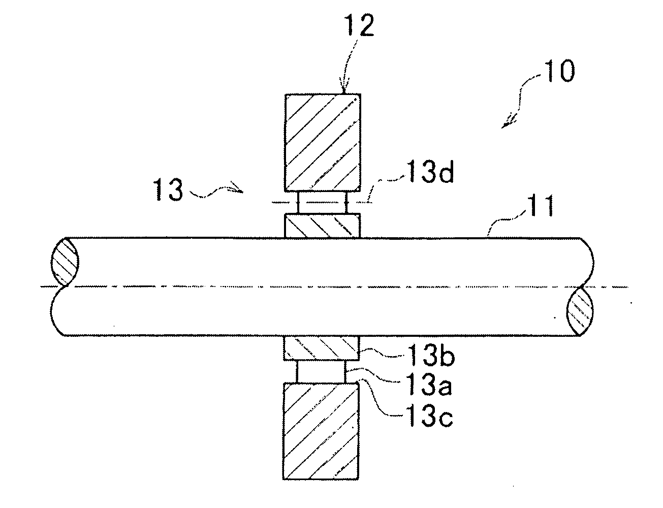
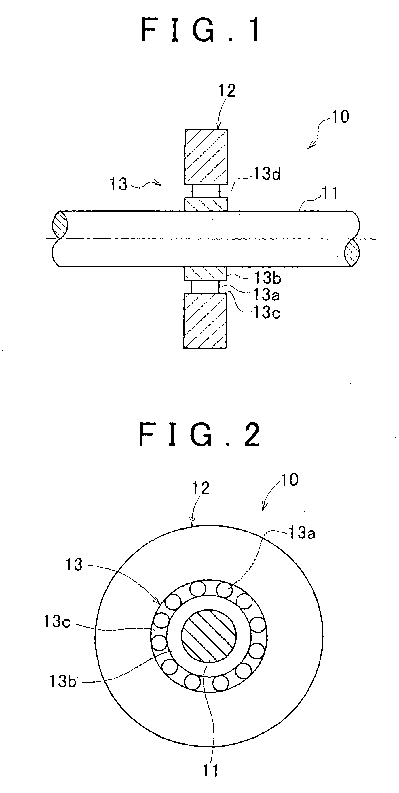
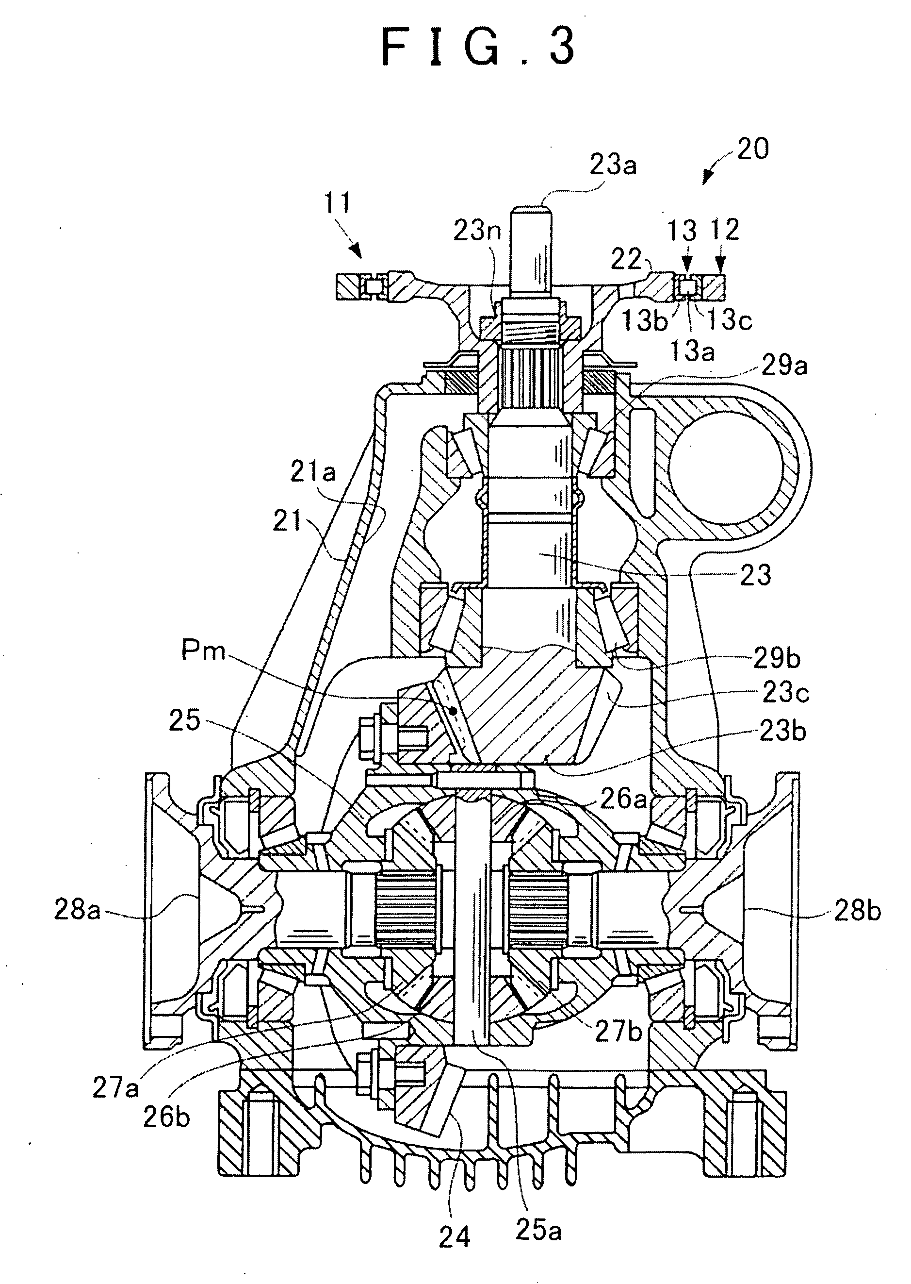
[0045]FIG. 1 is a schematic lateral sectional view of a vibration damping device according to the first embodiment of the invention. FIG. 2 is a schematic front sectional view of the vibration damping device. FIG. 3 is a lateral sectional view of a power transmission device fitted with the vibration damping device according to the first embodiment of the invention. The vibration damping device according to this embodiment of the invention is applied to a mass damper for damping bending resonance which is fitted to a rear differential device of a rear-wheel-drive vehicle.

[0046]First of all, the construction of the vibration damping device will be described.

[0047]As shown in FIGS. 1 and 2, a vibration damping device 10 is equipped with a mass body 12 disposed spaced apart from a rotational center axis CL of a rotary shaft 11 by a certain distance, and a rolling bearing 13 as a sup...


PUM


Abstract

A vibration damping device is equipped with a mass body disposed spaced apart from a rotational center axis of a rotary shaft by a certain distance, and a rolling bearing that rotatably supports the mass body with respect to the rotary shaft and holds a support posture of the mass body with respect to the rotational center axis of the rotary shaft constant.

Description

INCORPORATION BY REFERENCE[0001]The disclosure of Japanese Patent Application No. 2008-104881 filed on Apr. 14, 2008 including the specification, drawings and abstract is incorporated herein by reference in its entirety.BACKGROUND OF THE INVENTION[0002]1. Field of the Invention[0003]The invention relates to a vibration damping device and a power transmission device, and more particularly, to a vibration damping device that damps vibrations of a rotary shaft in a translational direction other than a rotational direction thereof using an inertial mass (mass body), and a power transmission device fitted with the vibration damping device.[0004]2. Description of the Related Art[0005]As a vibration damping device that exerts a vibration damping effect in the vicinity of a resonance frequency of a vibration system, a dynamic vibration absorber composed of an inertial mass and an elastic body is often employed. For example, there is known a vibration damping device with an inertial mass and...

Claims


Application Information

Patent Timeline
Patent Type & Authority Applications(United States)
IPC IPC(8): F16H48/08
CPCY10T74/2131Y10T74/2126Y10T464/50Y10T74/2121F16H48/42Y10T74/19865F16F15/1485F16H48/08Y10T74/2132F16F15/10
Inventor MOCHIHARA, TAKAHIRO
Owner TOYOTA JIDOSHA KK
Why Eureka
Try Eureka