Vibrating micro-mechanical sensor of angular velocity
- Summary
- Abstract
- Description
- Claims
- Application Information
AI Technical Summary
Benefits of technology
Problems solved by technology
Method used
Image
Examples
Embodiment Construction
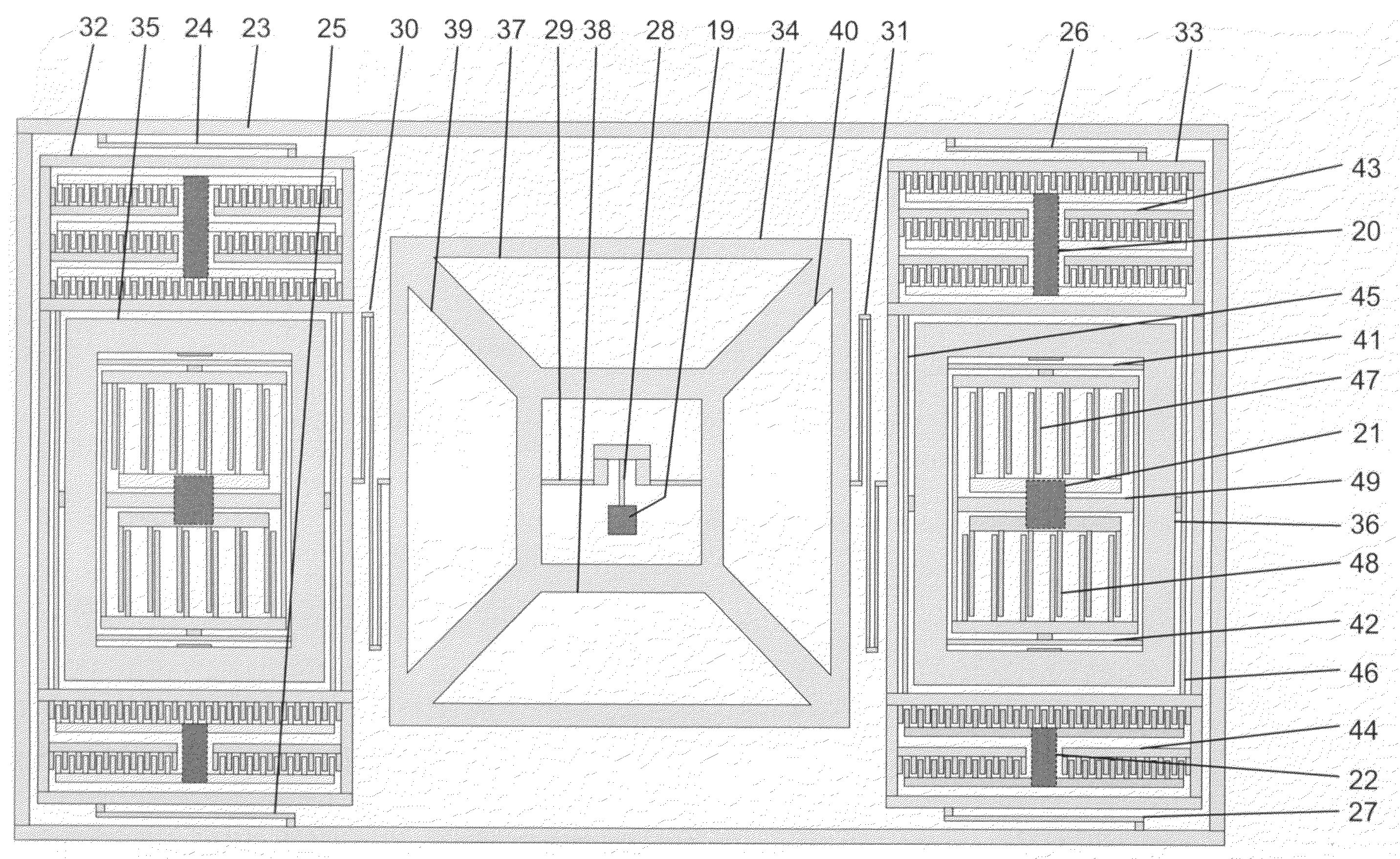
[0037]FIG. 4 shows a diagram of the functional structure of a vibrating micro-mechanical sensor of angular velocity with three axes according to the invention. The depicted vibrating micro-mechanical sensor of angular velocity with three axes according to the invention comprises a rotation mass 34, which is supported at the center to a support structure 19 by means of springs 28, 29 and supported in the X axis direction to excitation frame structures 32, 33 by means of springs 30, 31. The rotation mass 34 further comprises electrodes 37-40. Additionally, the vibrating micro-mechanical sensor of angular velocity with three axes according to the invention comprises linear masses 35, 36, which are supported in the X axis direction to the excitation frame structures 32, 33 by means of springs 45, 46. Said excitation frame structures 32, 33 are supported in the Y axis direction to a frame 23 around the edge of the sensor by means of bending springs 24-27. Additionally, the vibrating micr...
PUM
 Abstract
Description
Claims
Application Information
 - R&D
- Intellectual Property
- Life Sciences
- Materials
- Tech Scout
- Unparalleled Data Quality
- Higher Quality Content
- 60% Fewer Hallucinations
Browse by: Latest US Patents, China's latest patents, Technical Efficacy Thesaurus, Application Domain, Technology Topic, Popular Technical Reports.
© 2025 PatSnap. All rights reserved.Legal|Privacy policy|Modern Slavery Act Transparency Statement|Sitemap|About US| Contact US: help@patsnap.com


