Legged robot

a robot and trunk technology, applied in the field of legged robots, can solve the problems of prone to wobble of the trunk link, and achieve the effect of more stable trunk link

Inactive Publication Date: 2009-10-22
TOYOTA JIDOSHA KK
View PDF26 Cites 12 Cited by
  • Summary
  • Abstract
  • Description
  • Claims
  • Application Information

AI Technical Summary

Benefits of technology

[0024]In general, it is known that in the ordinary seated attitude of a human, the center of gravity of the human is located near the waist. Hence, by disposing the seat in the foregoing configuration, the center of gravity of the seated rider can be located below the rotation center of the uppermost pitch joint. Taken together with the fact that the center of gravity of the trunk link is also located below the rotation center of the uppermost pitch joint, this means that the combined center of gravity of the trunk link and the rider can be located below the rotation center of the uppermost pitch joint. This makes the trunk link more stable when the rider seats thereon. Thus, a legged robot whose trunk link is not prone to wobble even when the robot is walking while carrying a rider can be realized.
[0025]With the technology disclosed herein, a legged robot can be provided whose trunk link is not prone to wobble during walking.

Problems solved by technology

This means that the legged robot of Patent Document 1 has a structure in which, when it walks, its trunk link is prone to wobble.

Method used


Image

  • Legged robot
  • Legged robot
  • Legged robot

Examples


first embodiment

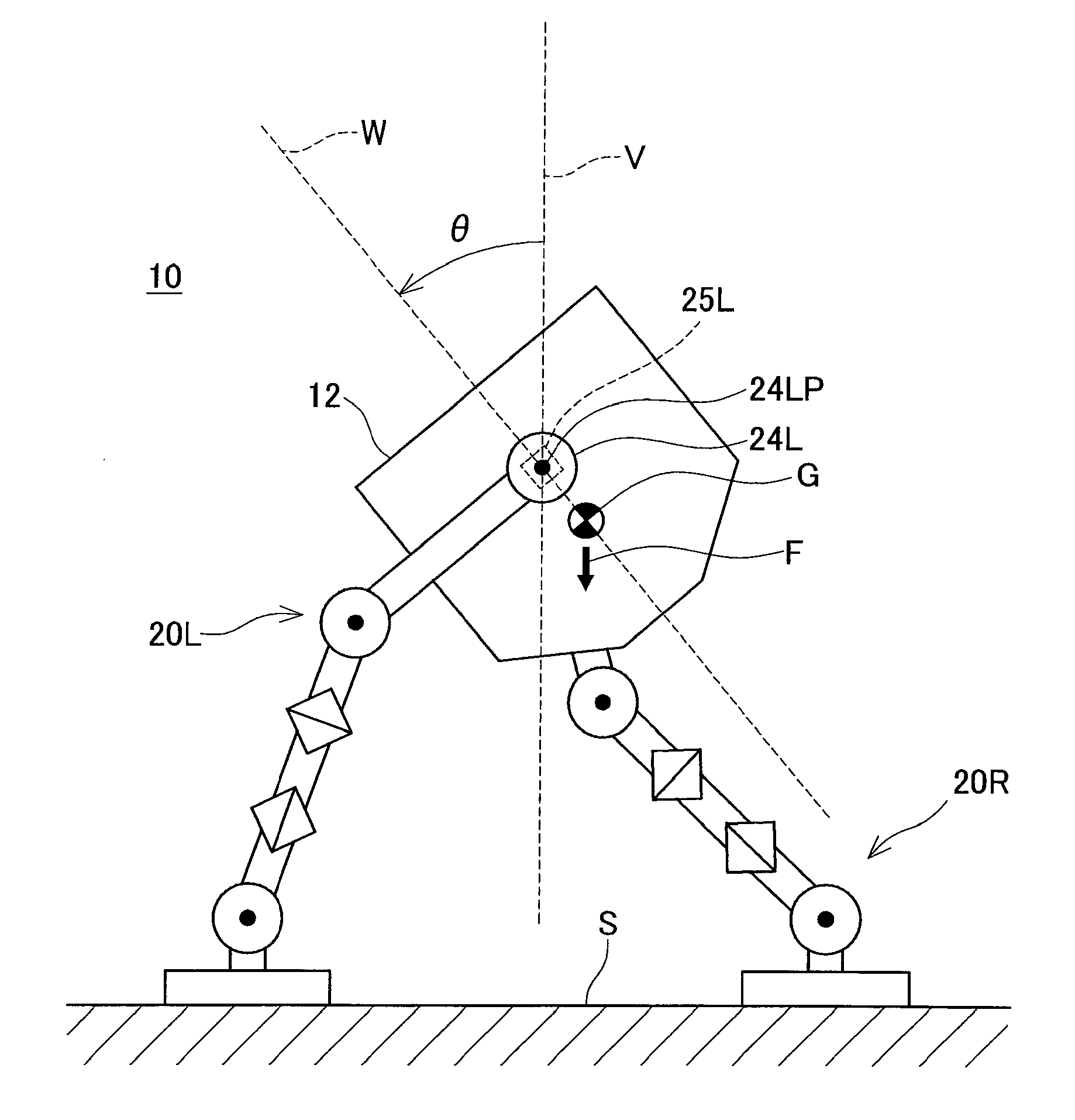
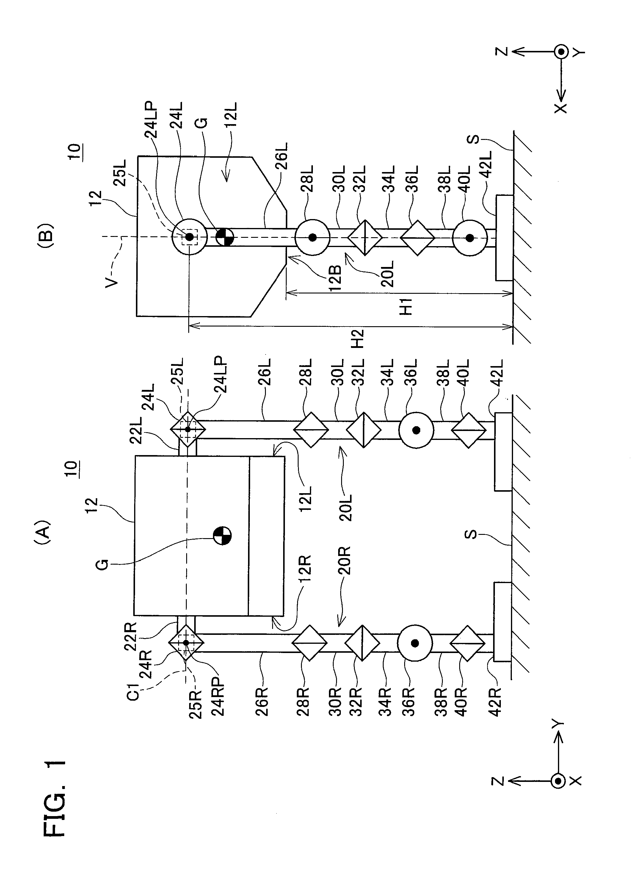
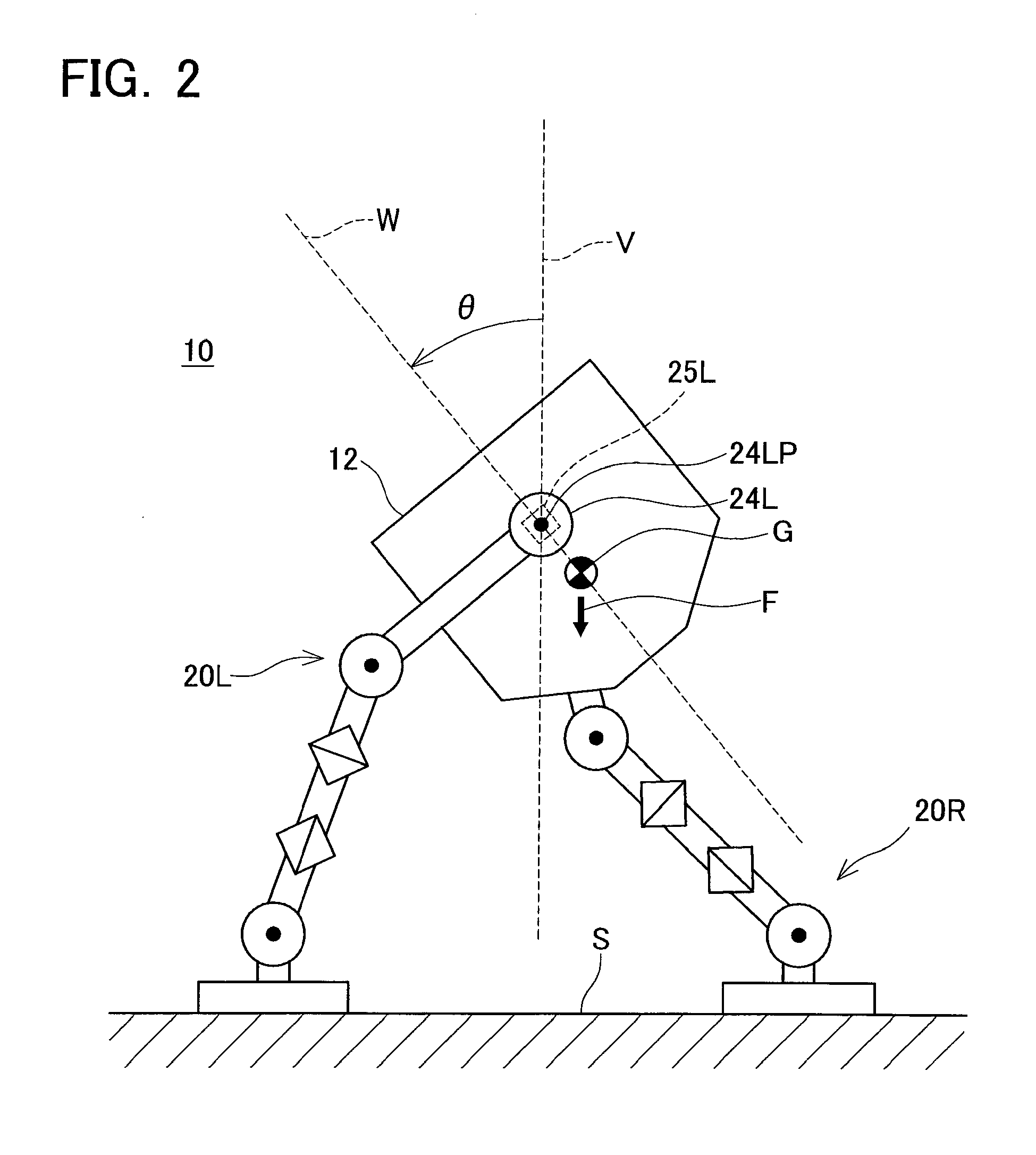
[0044]A legged robot 10 according to a first embodiment of the present invention will now be described, with reference to the accompanying drawings. FIG. 1(A) is a front view of the legged robot 10, and FIG. 1(B) is a side view of the legged robot 10. Note that in FIG. 1(B), indication of those parts that are hidden by the parts in the foreground of the drawing is omitted.

[0045]The legged robot 10 has a trunk link 12 and a pair of legs (right leg 20R and left leg 20L). Each leg has a plurality of links and a plurality of joints, as will be described hereafter.

[0046]First of all, a coordinate system will be described. In FIGS. 1(A) and 1(B), an XYZ coordinate system constituting a right-handed orthogonal coordinate system is shown. The XYZ coordinate system is a coordinate system that has an origin fixed to the trunk link 12 of the legged robot 10. The X-axis extends forward from the trunk link 12, and is termed a “roll axis”. The Y-axis extends in the lateral direction of the trunk ...

second embodiment

[0067]A second embodiment of the present invention will now be described. FIG. 4 is a side view of a legged robot 110 according to the second embodiment. The legged robot 110 has, in the interior of the trunk link 112 thereof, a seat 114 on which a rider H sits. The external form of the trunk link 112 and the structure of the legs 20L and 20R in the legged robot 110 are the same as those in the legged robot 10 according to the first embodiment, and descriptions thereof are therefore omitted. Note that, in FIG. 4, the right leg 20R is located behind the left leg 20L and therefore is not shown.

[0068]In the legged robot 110, the rotation centers 24LP and 24RP of the first left joint 24L and the first right joint 24R, which are the uppermost pitch joints, are also located above the center of gravity G of the trunk link 112, as in the legged robot 10 according to the first embodiment. Note that the first right joint 24R and the rotation center 24RP thereof are not shown in FIG. 4. A seat...

third embodiment

[0071]A third embodiment of the present invention will now be described with reference to the accompanying drawings. FIG. 5 shows three views (a top view, a side view and a rear view) of a legged robot 210 according to the third embodiment. FIG. 5(A) is a top view of the legged robot 210, FIG. 5(B) is a side view of the legged robot 210, and FIG. 5(C) is a rear view of the legged robot 210.

[0072]The legged robot 210 has a trunk link 212 and a pair of legs (a left leg 220L and a right leg 220R). The bottom surface 212a of the trunk link 212 is provided with sliding joints 216L and 216R that correspond to the legs 220L and 220R, respectively. The sliding joints 216L and 216R slidably connect respective one ends 224La and 224Ra of the legs 220L and 220R to the trunk link 212.

[0073]The structure of the left leg 220L will now be described. The left leg 220L has a plurality of links 221L, 222L, 224L, a plurality of rotary joints 230L, 232L, 234L, 236L, and a sliding joint 216L. The first ...


PUM


Abstract

A legged robot is provided whose trunk link is not prone to wobble in the front-back direction during walking. The legged robot is equipped with a trunk link and a pair of legs. Each leg has a pitch joint capable of rotating the connected links in a plane that intersects with a line extending in a lateral direction of the robot. Rotation centers of the pitch joints are located above a center of gravity of the trunk link. The legged robot walks mainly by swinging the legs backward and forward around such rotation centers. Hence, the trunk link wobbles mainly in the front-back direction around the rotation centers as the robot walks. Because the center of gravity of the trunk link is located below the rotation centers, the gravitational force acting on the trunk link acts in a direction to suppress swinging of the trunk link during walking. Due to this, the trunk link of the legged robot is not prone to wobble in the front-back direction during walking.

Description

CROSS-REFERENCE TO RELATED APPLICATION[0001]This application claims priority to Japanese Patent Application No. 2006-207471, filed on Jul. 31, 2006, the contents of which are hereby incorporated by reference into the present application.BACKGROUND OF THE INVENTION[0002]1. Field of the Invention[0003]The present invention relates to a legged robot having a trunk link and a pair of legs connected to the trunk link. The legged robot is sometimes termed simply “robot” herein.[0004]2. Description of the Related Art[0005]Legged robots having a pair of legs connected to a trunk link are being developed. Each leg has a plurality of links. Furthermore, a plurality of joints is disposed in each leg. Each joint connects at least two links, and rotates the connected links relative to each other by using the power that is supplied thereto. In some cases, the links connected by the joints are links composing a leg, while in other cases, they consist of the trunk link and a link composing a leg. T...

Claims


Application Information

Patent Timeline
Patent Type & Authority Applications(United States)
IPC IPC(8): B25J17/00
CPCY10T74/20329B62D57/032
Inventor SUGA, KEISUKEOGAWA, AKIRA
Owner TOYOTA JIDOSHA KK
Why Eureka
Try Eureka