
Mask support, mask assembly, and assembly comprising a mask support and a mask

a mask and mask assembly technology, applied in the field of mask support for supporting a mask, can solve the problems of limited reuse of mask frames having mask foils soldered thereto, and inability to reuse mask foils at all, so as to achieve convenient handling and exchange

Inactive Publication Date: 2009-10-22
APPLIED MATERIALS INC
View PDF4 Cites 17 Cited by
  • Summary
  • Abstract
  • Description
  • Claims
  • Application Information

AI Technical Summary

Benefits of technology

[0007]It is an object of the present invention to provide an improved mask assembly which allows easy handling and exchange of masks used for the production of OLED devices, particularly for the production of optical devices and displays, wherein the mask assembly may be adapted to provide a required stretching force for a particular mask.TECHNICAL SOLUTION
[0012]The invention is particularly useful for the production of OLED displays. By means of the invention a mask may be arranged in a stable position and stretched by providing an elastic element at each of the sides of the rectangular frame element. The present invention provides for a simple handling and exchange of structured mask foils, thus reducing the number of masks and mask frames required in a production process. Furthermore, the life cycle of a mask frame is extended due to the fact that detaching a mask is a gentle procedure and allows reuse of the mask and the mask frame.
[0013]When producing a mask in a conventional process the metal foil is positioned in a clamping fixture for processing, i.e. for providing a particular structure on the mask. The clamping fixture is particularly provided for processing the mask, whereas in the present invention the inventive mask support may be used for producing a mask as well as for using the mask in a coating process. Therefore, the number of process steps may be reduced, particularly detaching the mask from the clamping fixture after the production of the mask and attaching the mask to another frame for the coating process.
[0020]In a preferred embodiment of the invention the curved portion of the first elastic element and the curved portion of the second elastic element comprise a different number of curves. Varying the number of curves, e.g. varying the number of meanders along the length of the elastic elements between the mounting edge and the first engagement means, allows for a defined adjustment of the spring stiffness and / or spring deflection / spring travel.
[0029]The mask may be a laminar shadow mask, particularly a shadow mask processed from a metal sheet. A laminar mask is a shadow mask composed of a thin metal mask sheet which has a number of apertures to allow coating particles to pass the mask and form a pattern of material on a substrate. When using a mask, the apertures are polluted after some coating cycles. The present invention provides for an easy handling and exchange of masks from a mask support and for a quick attachment of a mask to a mask support.

Problems solved by technology

It is known that the production and the use of shadow masks in an OLED process cause considerable costs.
Furthermore, the reuse of mask frames having mask foils soldered thereto is limited due to the fact that exchanging a mask foil requires removal of material from the mask frame.
Reusing the mask foils is not possible at all.
On the other hand, exchanging a mask foil fixed to the frame by a screw fitting connection is quite elaborate and time consuming.

Method used


Image

  • Mask support, mask assembly, and assembly comprising a mask support and a mask
  • Mask support, mask assembly, and assembly comprising a mask support and a mask
  • Mask support, mask assembly, and assembly comprising a mask support and a mask

Examples


Embodiment Construction

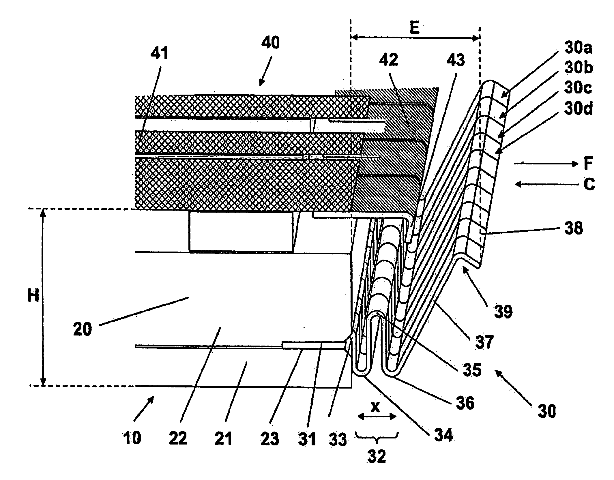
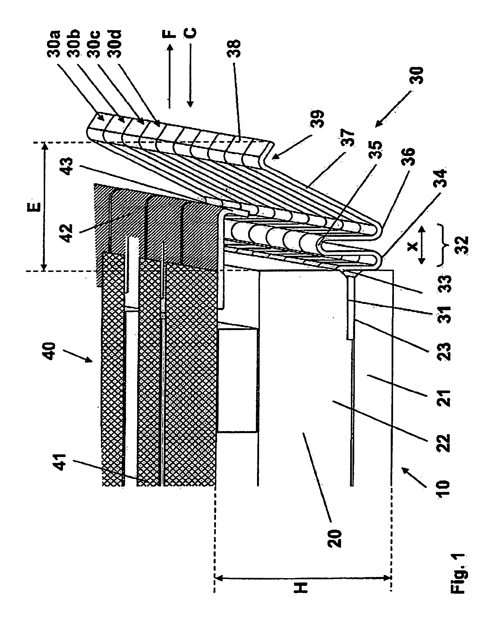
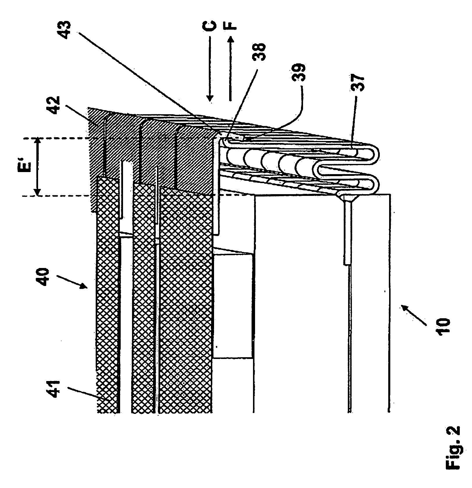
[0040]FIG. 1 illustrates a portion of a mask support 10 comprising a frame element 20 and an elastic element 30. The elastic element 30 is fixed to the frame element 20.

[0041]The frame element 20 comprises a first frame portion 21 and a second frame portion 22 and may have a rectangular or square configuration.

[0042]The elastic element 30 is a component integrally formed of a flexible material. It comprises a mounting edge portion 31 which extends into a recess 23 which is provided between the first frame portion 21 and the second frame portion 22 of the frame element 20 along a marginal side of the frame element 20. The mounting edge portion 31 is clamped between the first frame portion 21 and the second frame portion 22. One or a plurality of elastic elements 30 may be arranged along a marginal edge of the frame element 20 for enabling the elastic element to fix and stretch a mask attached to the mask support 10 in every direction.

[0043]Furthermore, the elastic element 30 comprise...


PUM

PropertyMeasurementUnit
angleaaaaaaaaaa
angleaaaaaaaaaa
elasticaaaaaaaaaa

Abstract

A mask support 10 comprises a frame element 20 and an elastic element 30. The elastic element 30 is fixed to the frame element 20. The elastic element 30 is a component integrally formed of a flexible material. It comprises a lever or arm portion 37 having a first engagement protrusion 38 extending in an angle of approximately 90° from the free end of the arm portion 37. A mask assembly 40 comprises a laminar mask 41, e.g. manufactured from a thin metal foil, and connecting elements 42. The connecting elements 42 include an engagement portion 43 for engagement with the engagement protrusion 38 of the elastic element 30. The mask 41 may be attached / stretched to the mask support 10 as well as to detached from the mask support 10 comfortably.

Description

FIELD OF THE INVENTION[0001]The present invention relates to a mask support for supporting a mask, particularly for supporting a laminar mask for use in an OLED coating device, comprising a plurality of elastic elements, wherein both a first elastic element and a second elastic element of the plurality of elastic elements comprise a lever or arm portion and a first engagement means arranged at the first elastic element and the second elastic element, respectively, for engagement with a corresponding second engagement means provided at the mask assembly for carrying the mask, wherein the elastic elements are configured for fixing the mask to the frame element and for stretching the mask supported in the frame element.PRIOR ART[0002]In the production of OLED devices, e.g. OLED displays, shadow masks are used for generating a coating having a patterned structure on a substrate. Usually the masks are mask foils made of a thin metal sheet. In order to provide a reliable support and adjus...

Claims


Application Information

Patent Timeline
Patent Type & Authority Applications(United States)
IPC IPC(8): B05C11/00
CPCC23C14/042G03F7/12B05C21/005Y10T29/49863H05B33/10Y10T29/49826C23C14/04
Inventor LANDGRAF, HEIKESCHUESSLER, UWEBANGERT, STEFAN
Owner APPLIED MATERIALS INC
Learn More