Magnetic ranging while drilling using an electric dipole source and a magnetic field sensor

a magnetic field sensor and dipole source technology, applied in the direction of directional drilling, survey, borehole/well accessories, etc., can solve the problems of difficult location of the closest approach point between the two wells, and inconvenient operation of the dipole sour

Inactive Publication Date: 2009-10-22
SCHLUMBERGER TECH CORP
View PDF40 Cites 35 Cited by
  • Summary
  • Abstract
  • Description
  • Claims
  • Application Information

AI Technical Summary

Problems solved by technology

Heavy oil may be too viscous in its natural state to be produced from a conventional well.
Using many conventional techniques, the point of closest approach between the two wells may be difficult to locate or the location of the point of closest approach may be imprecise.
Moreover, the relative distance between the injector and producer wells of an X-SAGD or THAI well pair may affect potential recovery.
However, if the wells are located too near to one another, steam or air from the injector well may shunt into the producer well, and if the wells are located too far from one another, the heated heavy oil may not extend to the producer well.
Using conventional techniques, it may be difficult to accurately drill one well perpendicular to another well.

Method used


Image

  • Magnetic ranging while drilling using an electric dipole source and a magnetic field sensor
  • Magnetic ranging while drilling using an electric dipole source and a magnetic field sensor
  • Magnetic ranging while drilling using an electric dipole source and a magnetic field sensor

Examples


Embodiment Construction

[0030]One or more specific embodiments of the present invention are described below. In an effort to provide a concise description of these embodiments, not all features of an actual implementation are described in the specification. It should be appreciated that in the development of any such actual implementation, as in any engineering or design project, numerous implementation-specific decisions must be made to achieve the developers' specific goals, such as compliance with system-related and business-related constraints, which may vary from one implementation to another. Moreover, it should be appreciated that such a development effort might be complex and time consuming, but would nevertheless be a routine undertaking of design, fabrication, and manufacture for those of ordinary skill having the benefit of this disclosure.

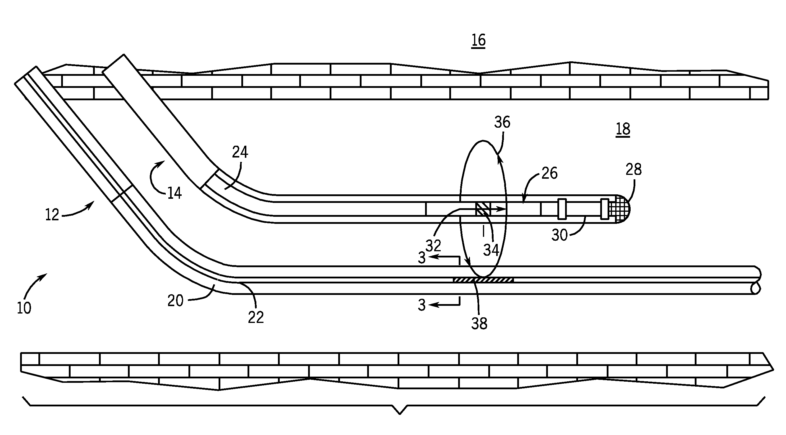
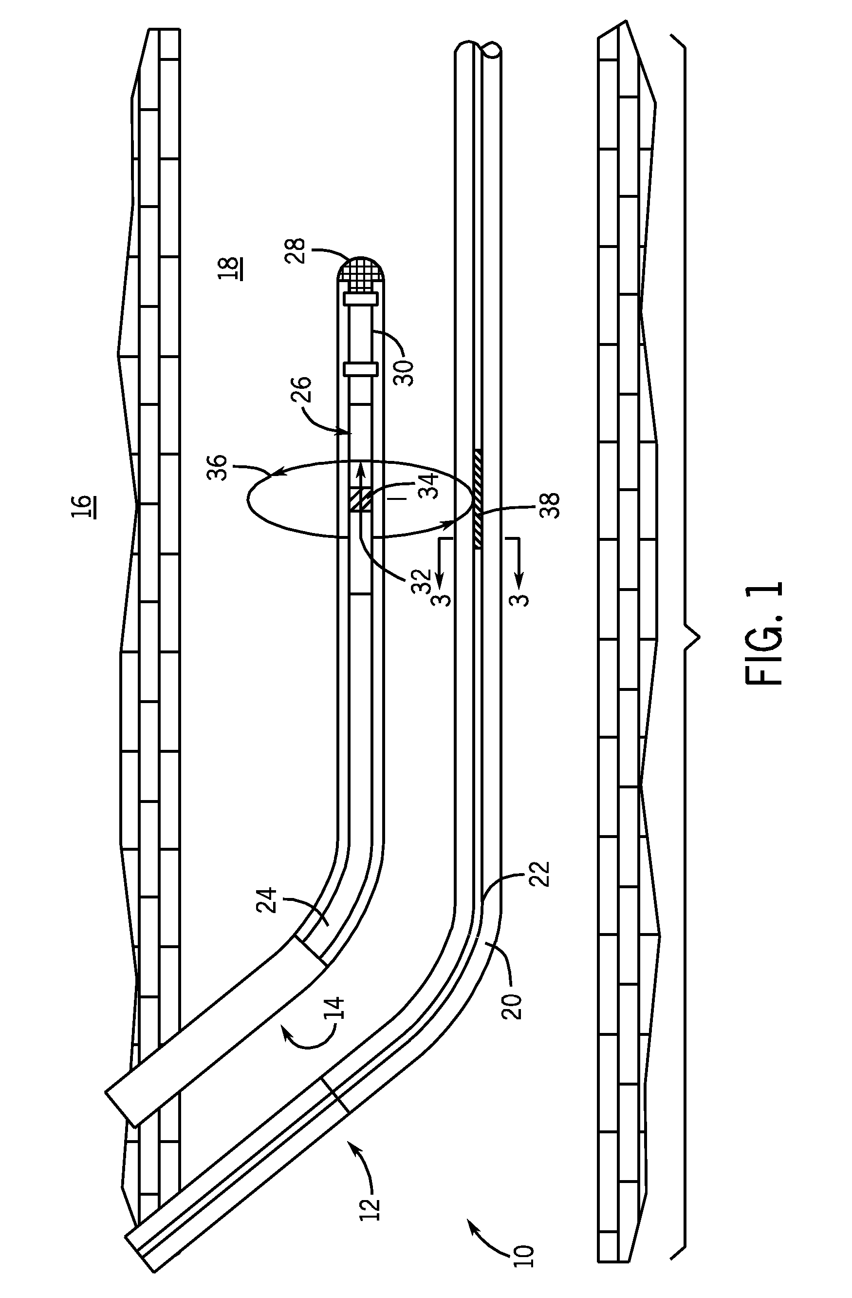
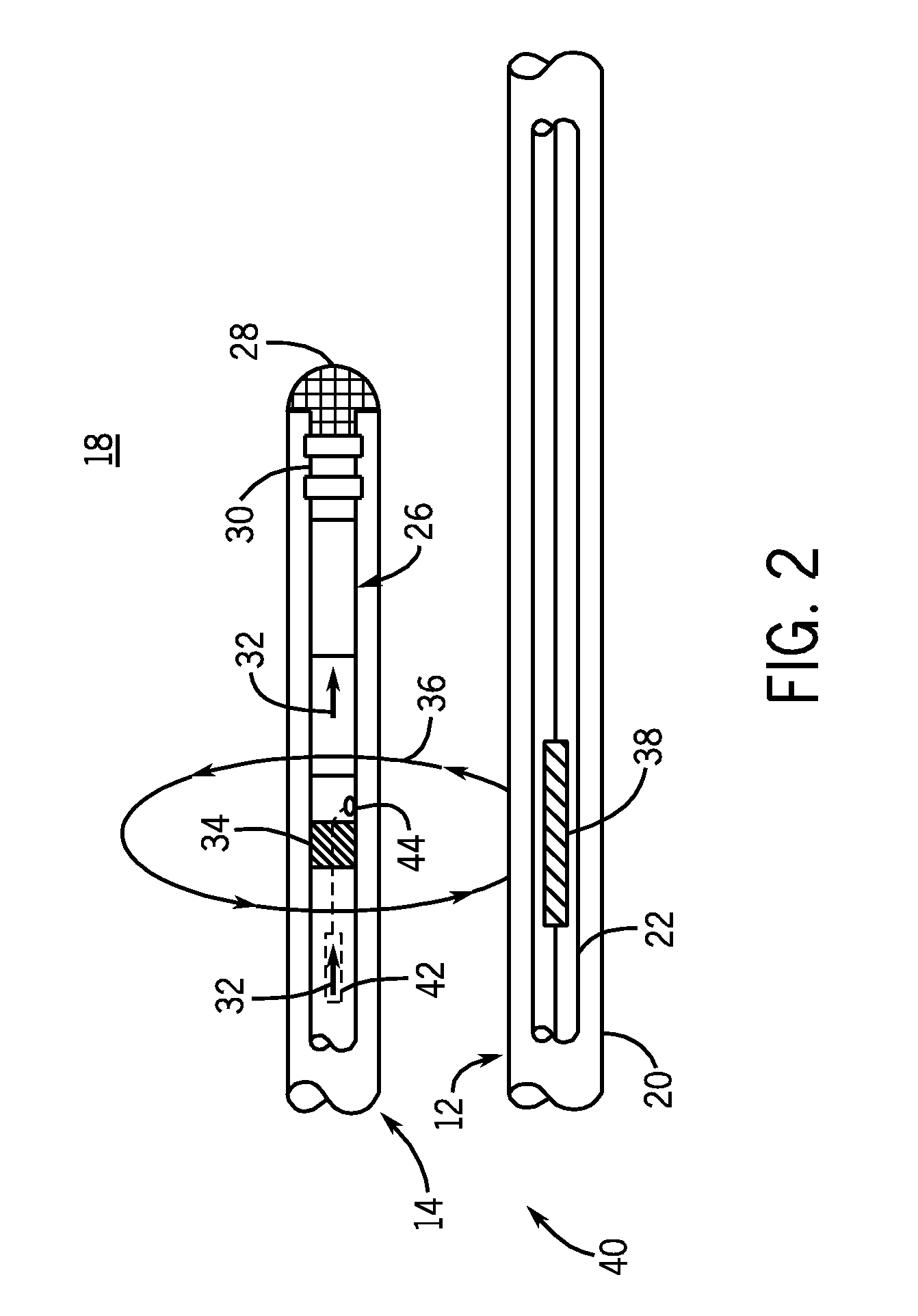
[0031]As used herein, the term “first well” (labeled numeral 12) refers to a generally horizontal existing well, “vertical well” (labeled numeral 52) refers t...


PUM


Abstract

A system and methods for drilling a well in a field having an existing well are provided. In accordance with one embodiment, a method of drilling a new well in a field having an existing well includes drilling the new well using a bottom hole assembly (BHA) having a drill collar divided by an insulated gap, generating a current on the drill collar of the BHA while drilling the new well, and measuring from the existing well a magnetic field caused by the current on the drill collar of the BHA. Using measurements of the magnetic field, the relative position of the new well to the existing well may be determined.

Description

BACKGROUND OF THE INVENTION[0001]The present invention relates generally to well drilling operations and, more particularly, to well drilling operations using magnetic field measurements from an electric dipole to ascertain the relative location of a new well to an existing well.[0002]Heavy oil may be too viscous in its natural state to be produced from a conventional well. To produce heavy oil, a variety of techniques may be employed, including, for example, Steam Assisted Gravity Drainage (SAGD), Cross Well Steam Assisted Gravity Drainage (X-SAGD), or Toe to Heel Air Injection (THAI). While SAGD wells generally involve two parallel horizontal wells, X-SAGD and THAI wells generally involve two or more wells located perpendicular to one another.[0003]X-SAGD and THAI techniques function by employing one or more wells for steam injection or air injection, respectively, known as “injector wells.” The injector wells pump steam or air into precise locations in a heavy oil formation to he...

Claims


Application Information

Patent Timeline
Patent Type & Authority Applications(United States)
IPC IPC(8): E21B47/022
CPCE21B47/02216E21B43/2406E21B47/0228
Inventor CLARK, BRIANGOSWAMI, JAIDEVA C.
Owner SCHLUMBERGER TECH CORP
Why Eureka
Try Eureka