Assembling Method of Tractor and Tractor

a technology of assembling method and hood, which is applied in the direction of tractors, jet propulsion mounting, manufacturing tools, etc., can solve the problems of poor operability, cumbersome assembly operation, and elongated assembly line, and achieve the effect of preventing the occurrence of damage to the body such as the hood

Inactive Publication Date: 2009-10-22
YANMAR CO LTD
View PDF25 Cites 15 Cited by
  • Summary
  • Abstract
  • Description
  • Claims
  • Application Information

AI Technical Summary

Benefits of technology

[0022]In this manner, the assembly line is divided into the main line and the sub lines, the parts to be assembled are preliminarily assembled in parallel as the first to fifth units on the sub lines, and these first to fifth units are merged and assembled together on the mainline. Accordingly, it is possible to shorten the main line which constitutes the assembly line and, at the same time, it is unnecessary to arrange a large number of operators and a large kinds of assembling members along the main line and hence, it is possible to simplify the assembling operation on the main line.
[0047]In this manner, by forming the front weight mounting portion which extends in the lateral direction on the front end portion of the front support body and, at the same time, by arranging the front weight mounting portion at the frontmost portion of the body, in a state that a front weight is removed from the front weight mounting portion (front-weight non-mounting state), the front weight mounting portion also functions as a bumper and hence, the occurrence of damages on the body such as hood can be prevented.

Problems solved by technology

(1) Since the assembling operation is performed on one-line assembly line, the assembly line becomes elongated.
(2) Since it is necessary to arrange parts to be sequentially assembled along the assembly line, the assembly operation becomes cumbersome.
(3) When a trouble occurs even at one portion of the assembly line, it is necessary to stop the whole assembly line thus exhibiting the poor operability.
However, in the above-mentioned tractor, since the dashboard support member, the pedal support member and the steering column support member are respectively mounted on the partition wall, from a viewpoint of the assembling order, there arises a drawback that the above-mentioned support member and support member cannot be mounted on the traveling body until the partition wall is mounted on the traveling body in an erected manner.
As a result, to consider the whole assembling operation of the tractor, the number of assembly man-hours is still large and the assembling operation is cumbersome.
Such a hot air shielding body gives rise to cumbersomeness that the hot air shielding body must be mounted at inner positions above the left and right sides of the support body while avoiding the interference with the fuel tank.
Further, the fuel tank is arranged in a bent manner above and behind the rear portion of the engine and hence, to perform the maintenance operation of the fuel tank, there arises cumbersomeness that both of the hood and the dashboard must be removed from the support body.
However, a distance in the lateral direction between the above-mentioned pair of left and right longitudinally extending members is set slightly wider than a lateral width between lower portions of left and right side walls of the engine in view of the assembling operation and hence, there arises a drawback that even when the longitudinally extending members are strongly fastened by the fastening bolts, the favorable hermetic sealing between the longitudinally extending member and the lower positions of left and right side walls cannot be ensured.
That is, since the favorable hermetic sealing cannot be ensured between the longitudinally extending members and lower portions of the left and right side wall of the engine, no friction force is generated between the longitudinally extending members and the engine.
Accordingly, all of a load of the engine is applied only to fastening bolts as a shearing force thus giving rise to a drawback that the fastening bolts may rupture.

Method used


Image

  • Assembling Method of Tractor and Tractor
  • Assembling Method of Tractor and Tractor
  • Assembling Method of Tractor and Tractor

Examples


Embodiment Construction

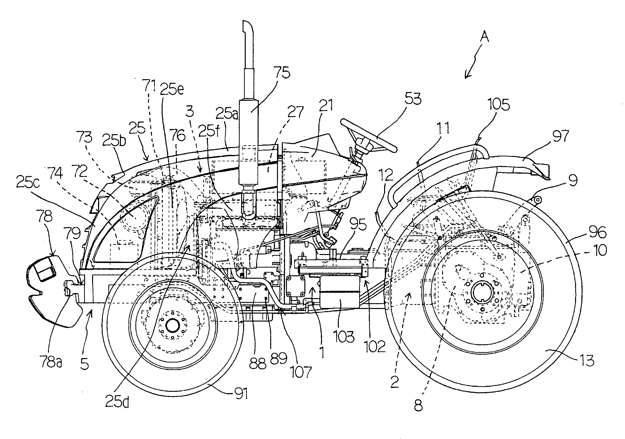
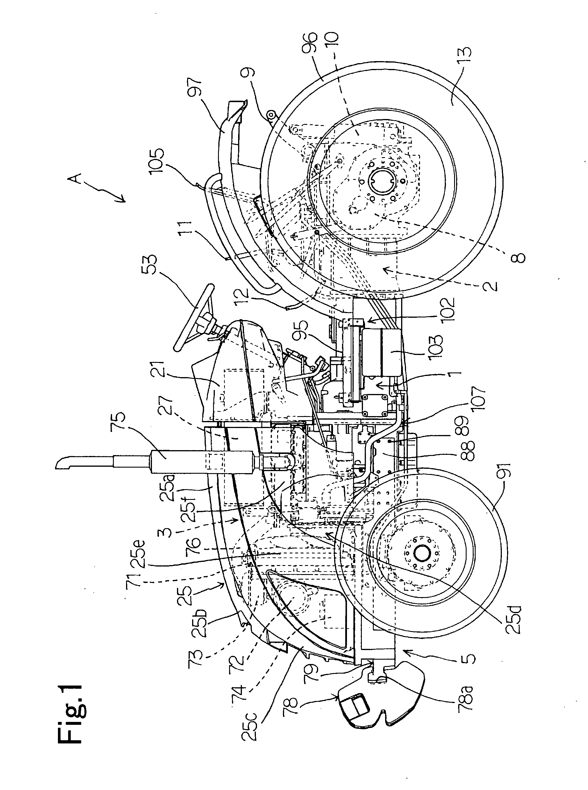
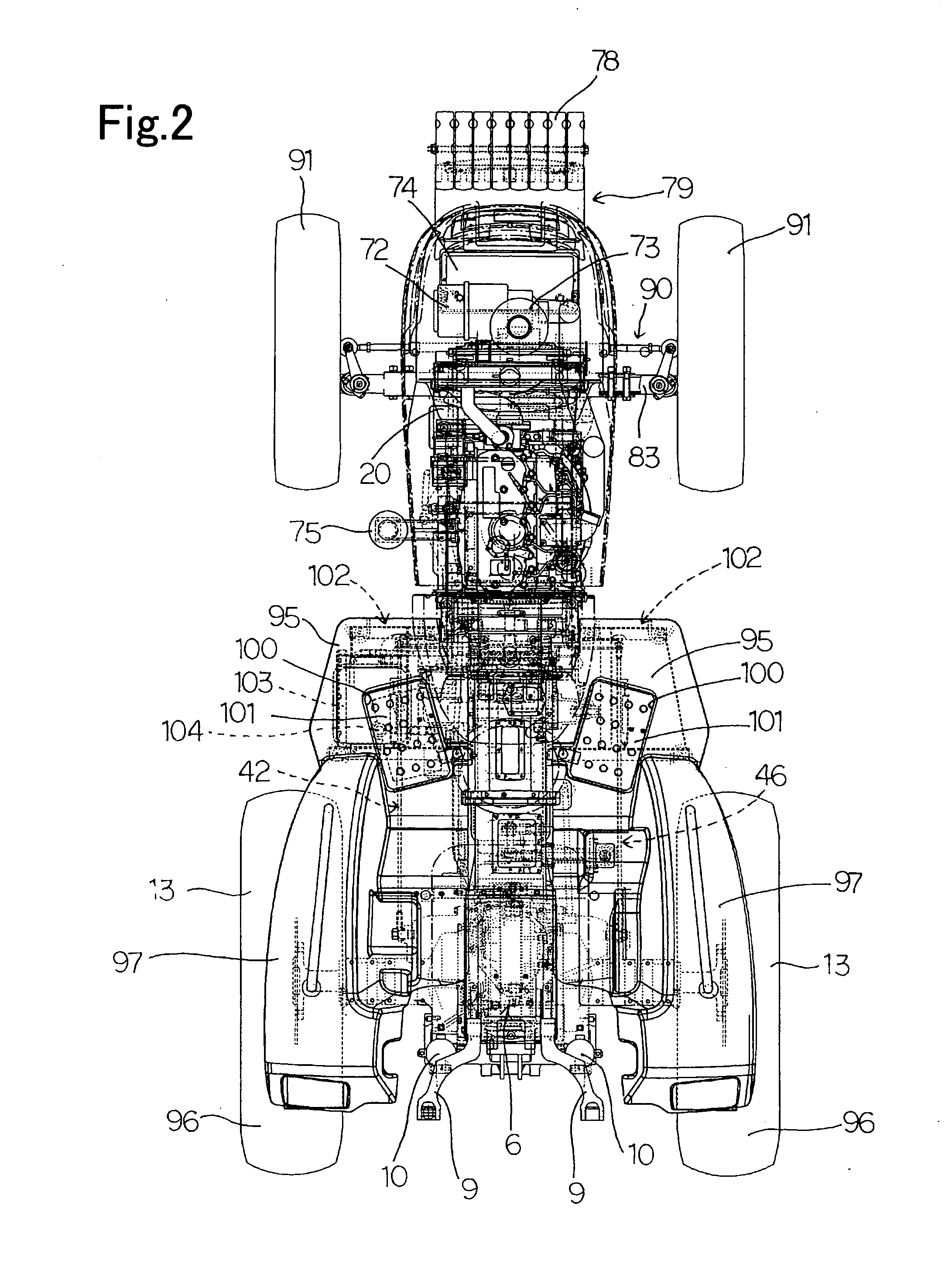
[0062]Symbol A shown in FIG. 1 and FIG. 2 indicates a tractor according to the present invention. The tractor A is, as also shown in FIG. 3, constituted by assembling a first unit U1 in which a clutch part 1 and a transmission part 2 are connected to each other, a second unit U2 in which parts such as a handle, pedals, a dashboard and a fuel tank are assembled to a prime mover part 3 by way of supporting members, a third unit U3 in which a front support body 5 and parts such as a battery and a radiator which are supported on the front support body 5 are assembled, a fourth unit U4 in which steps, fenders and the like are assembled together and a fifth unit U5 which constitutes a hood.

[0063]An assembly line is constituted of a main line and sub lines. The above-mentioned respective first to fifth units U1 to U5 are individually assembled preliminarily on the sub lines and, subsequently, these first to fifth units U1 to U5 are assembled together on the main line.

[0064]In this manner, ...


PUM

PropertyMeasurementUnit
weightaaaaaaaaaa
structureaaaaaaaaaa
rigidityaaaaaaaaaa

Abstract

The present invention aims at the shortening of a main line which constitutes an assembly line. To achieve such an object, in the present invention, an assembly line is constituted of a main line and sub lines, and a first unit which is constituted by connecting a clutch part and a transmission part, a second unit which constitutes a prime mover part, a third unit to which a support body and parts such as a handle, pedals, a dashboard, a fuel tank and the like which are supported on the support body are assembled, a fourth unit to which a front support body and parts such as a battery and a radiator which are supported on the front support body are assembled, a fifth unit to which steps, fenders and the like are assembled, and a sixth unit which is a hood are preliminarily assembled on sub lines and, thereafter, the above-mentioned first to sixth units are assembled together on the main line.

Description

BACKGROUND OF THE INVENTION[0001]1. Field of the Invention[0002]The present invention relates to a method for efficiently assembling a tractor and the structure of the tractor.[0003]2. Description of the Related Art[0004]Conventionally, as one mode of a method for assembling a tractor, there has been known a method in which the tractor is assembled on one-line assembly line based on the flow production (see patent document 1, for example).[0005]That is, on one-line assembly line, first of all, a body frame is assembled and, subsequently, parts which are to be mounted on the body frame are sequentially assembled to the body frame based on the flow production thus completing the tractor.[0006]However, the above-mentioned assembling method still has following drawbacks.[0007](1) Since the assembling operation is performed on one-line assembly line, the assembly line becomes elongated.[0008](2) Since it is necessary to arrange parts to be sequentially assembled along the assembly line, ...

Claims


Application Information

Patent Timeline
Patent Type & Authority Applications(United States)
IPC IPC(8): B62D65/02B60K37/00B62D25/10B60K15/00B60K5/00B60R16/04B23P21/00
CPCB62D49/0671Y10T29/49904B62D65/02
Inventor OKA, YOZOTAKAHASHI, NOBUAKI
Owner YANMAR CO LTD
Why Eureka
Try Eureka