Modified dimming LED driver

a technology of led drivers and dimming lights, which is applied in the direction of electric variable regulation, process and machine control, instruments, etc., can solve the problems of large changes, linear regulators are not very efficient circuits, and the level of forward current will degrade faster

Active Publication Date: 2009-10-22
BOCA FLASHER
View PDF2 Cites 95 Cited by
  • Summary
  • Abstract
  • Description
  • Claims
  • Application Information

AI Technical Summary

Problems solved by technology

LEDs driven at higher levels of forward current will degrade faster, and therefore have a shorter useful life, than the same LEDs driven at lower levels of forward current.
For this reason, linear regulators are not very efficient circuits when the input voltage is much larger than the required output voltage.
However, LEDs are not linear devices and small changes in voltage may result in large changes in current which correspondingly effect large changes in output intensity.
The lower power efficiency of linear regulators generally makes them a poor choice in large power systems and in systems where the input voltage is much larger than the required LED driving voltage.
As such, these systems typically do not employ them.
However, it requires control circuitry and user interface equipment which adds a level of cost and complexity to the lighting system.
However the dimming is very non-linear and these regulators are inefficient.
An even greater problem with dimming switching regulator drivers is that these circuits need a certain start-up voltage to operate.
As a result, some lights may flicker, some may be off and some may glow below the threshold voltage.
This is unacceptable in most lighting systems that are required to dim using standard ac dimming controllers.

Method used


Image

  • Modified dimming LED driver
  • Modified dimming LED driver
  • Modified dimming LED driver

Examples


Embodiment Construction

[0026]FIGS. 5-7 show the typical shapes of the ac voltage input presented to a light or lighting system by standard ac dimmers. FIG. 5 shows a forward-phase control chopped sinewave typical of most silicon controlled rectifier (SCR) type incandescent wall dimmers. FIG. 6 shows a reverse-phase waveform which is sometimes provided by dimmers made for electronic or capacitive loads. FIG. 7 shows the type of ac voltage waveform presented by an autotransformer, and some higher-end dimming systems designed for theater lighting. In all of these cases, it is the input voltage that is modified (reduced in amplitude or chopped out during part of the sinewave) in order to present a lower average or rms voltage to the load. As explained in the Background section, this type of dimming can cause non-linear and unpredictable results when it is used with a switcher regulator circuit as is often the case in LED lighting products.

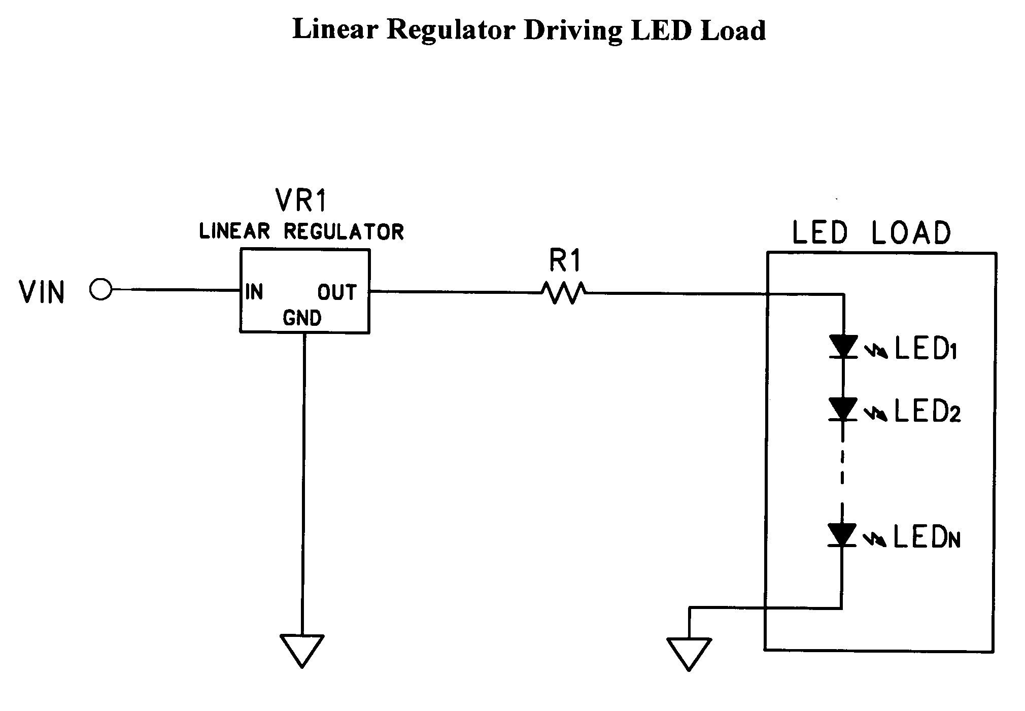
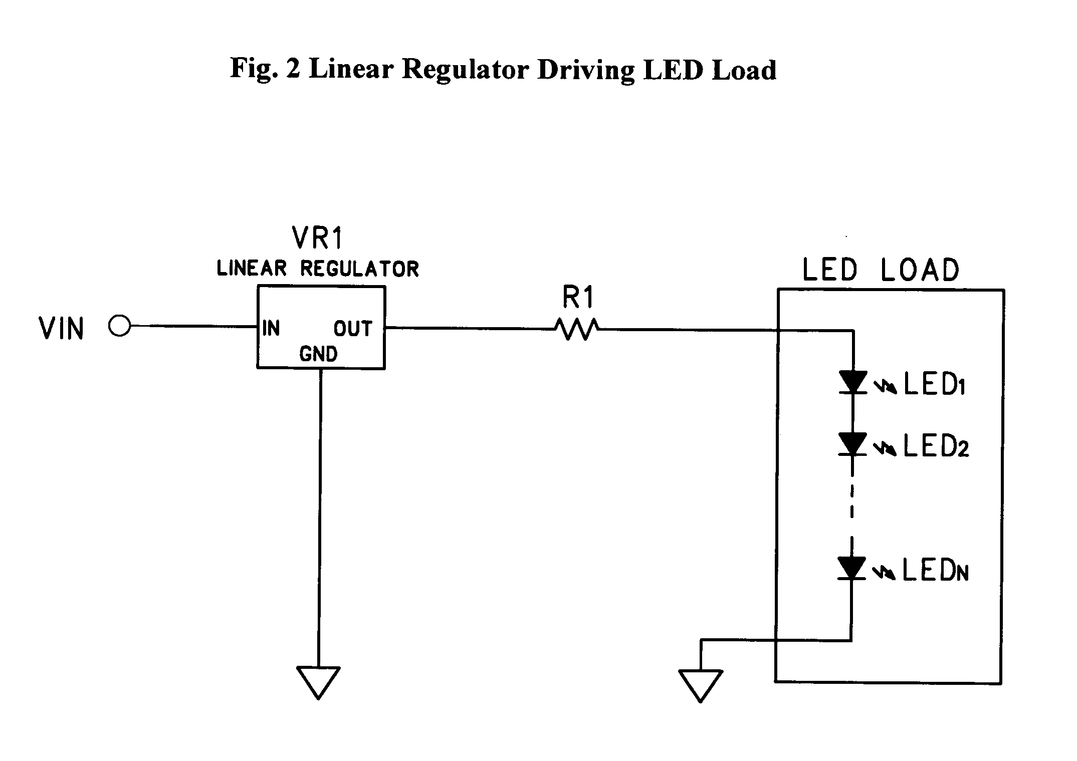
[0027]The present invention is best understood by starting with a typic...


PUM


Abstract

A driver circuit produces variable current output for an LED lighting system providing improved dimming capability and greater power efficiency when responding to industry standard lighting dimmers, through the use of an input voltage monitoring circuit which variably controls the current output of a switching regulator. Output current modulation methods such as analog, PWM, Pulse Frequency Modulation, or other digital modulation, and combination or hybrid methods such as that disclosed in U.S. Pat. No. 7,088,059 B2 may be employed. The current invention marries such output modulation techniques with a control method which is derived through intelligent monitoring of the input voltage waveform. The circuit and method described is adapted to higher current applications such as LED lighting systems using the latest high-power LEDs.

Description

PRIOR APPLICATION[0001]This current application is a utility application, filed from and benefiting from the earlier filed U.S. Provisional Application No. 61 / 071,150, filing date Apr. 15, 2008, titled Modified Dimming Led Driver. All of the disclosures of the Provisional application is incorporated herein by reference.FIELD OF THE INVENTION[0002]This invention relates to drivers for illumination devices such as LEDs (light emitting diodes). The use of LEDs in illumination systems is well known. These devices are especially useful for lighting components, systems, and finished goods. LED lighting is a fast growing segment of the lighting industry due to the efficiency, reliability and longevity of LEDs. Product usage applications include but are not limited to interior and exterior signage, cove lighting, architectural lighting, display case lighting, under water lighting, marine lighting, informational lighting, task lighting, accent lighting, ambient lighting and many others. The ...

Claims


Application Information

Patent Timeline
Patent Type & Authority Applications(United States)
IPC IPC(8): H05B37/02
CPCH05B33/0812Y02B20/345H05B33/0854H05B33/0815H05B45/10H05B45/3725H05B45/375H05B45/38H05B45/395Y02B20/30
Inventor MCKINNEY, STEVENGOLTMAN, ISAY
Owner BOCA FLASHER
Why Eureka
Try Eureka