
Working vehicle

a technology for working vehicles and generators, applied in the direction of motor/generator/converter stoppers, electric devices, propulsion using engine-driven generators, etc., can solve the problem of inability to use engines, and achieve the effect of improving work efficiency

Active Publication Date: 2009-10-22
TAKEUCHI SEISAKUSHOKK
View PDF8 Cites 36 Cited by
  • Summary
  • Abstract
  • Description
  • Claims
  • Application Information

AI Technical Summary

Benefits of technology

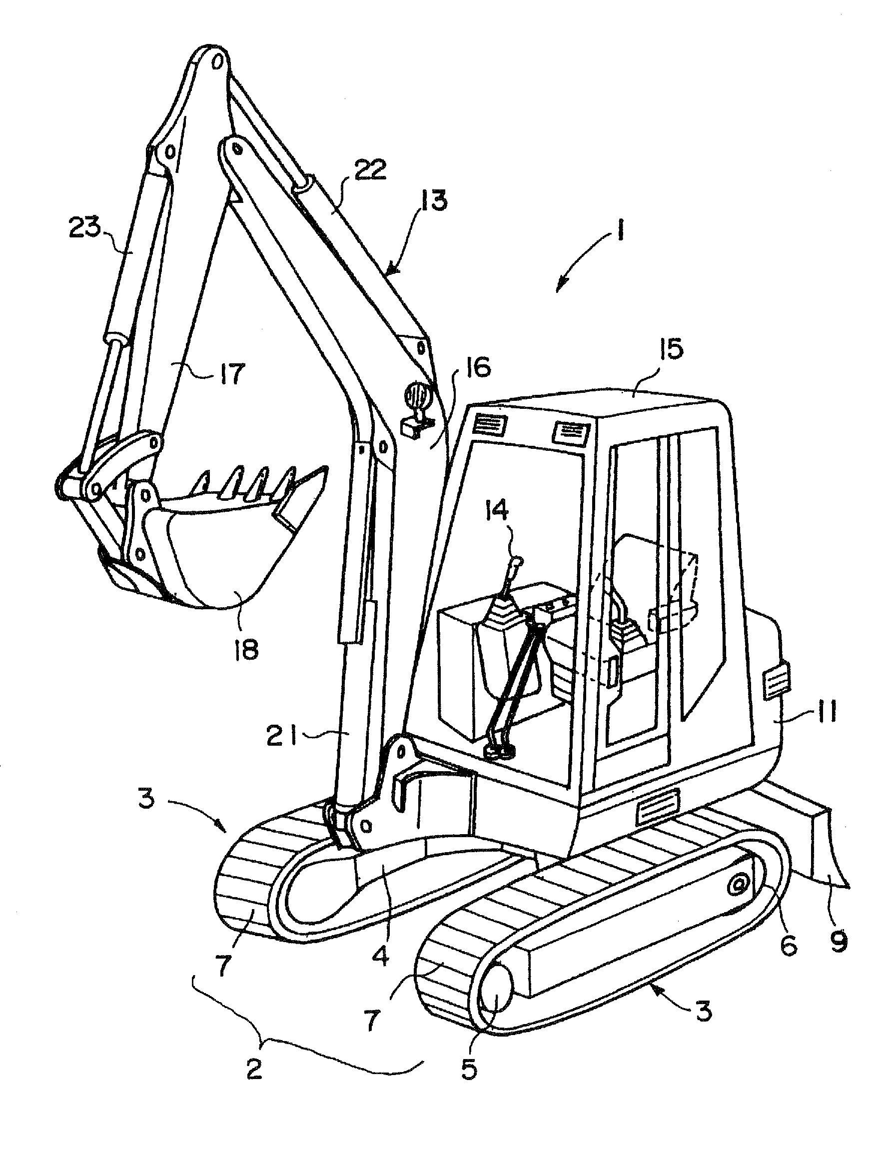
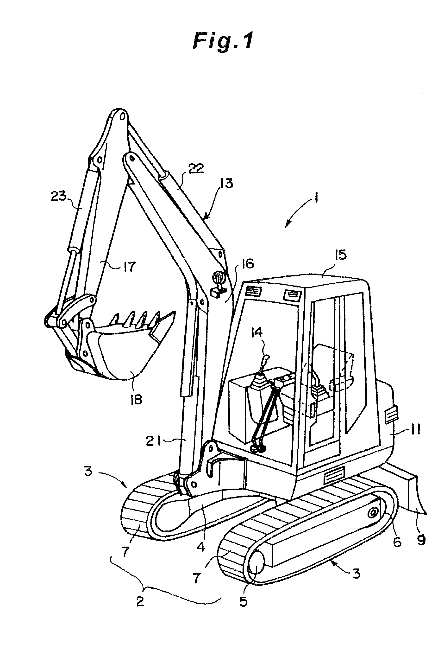
[0007]To solve the above problems, the working vehicle according to the present invention (for example, the crawler type power shovel 1 according to the embodiments) is a working vehicle operated by a hydraulic 
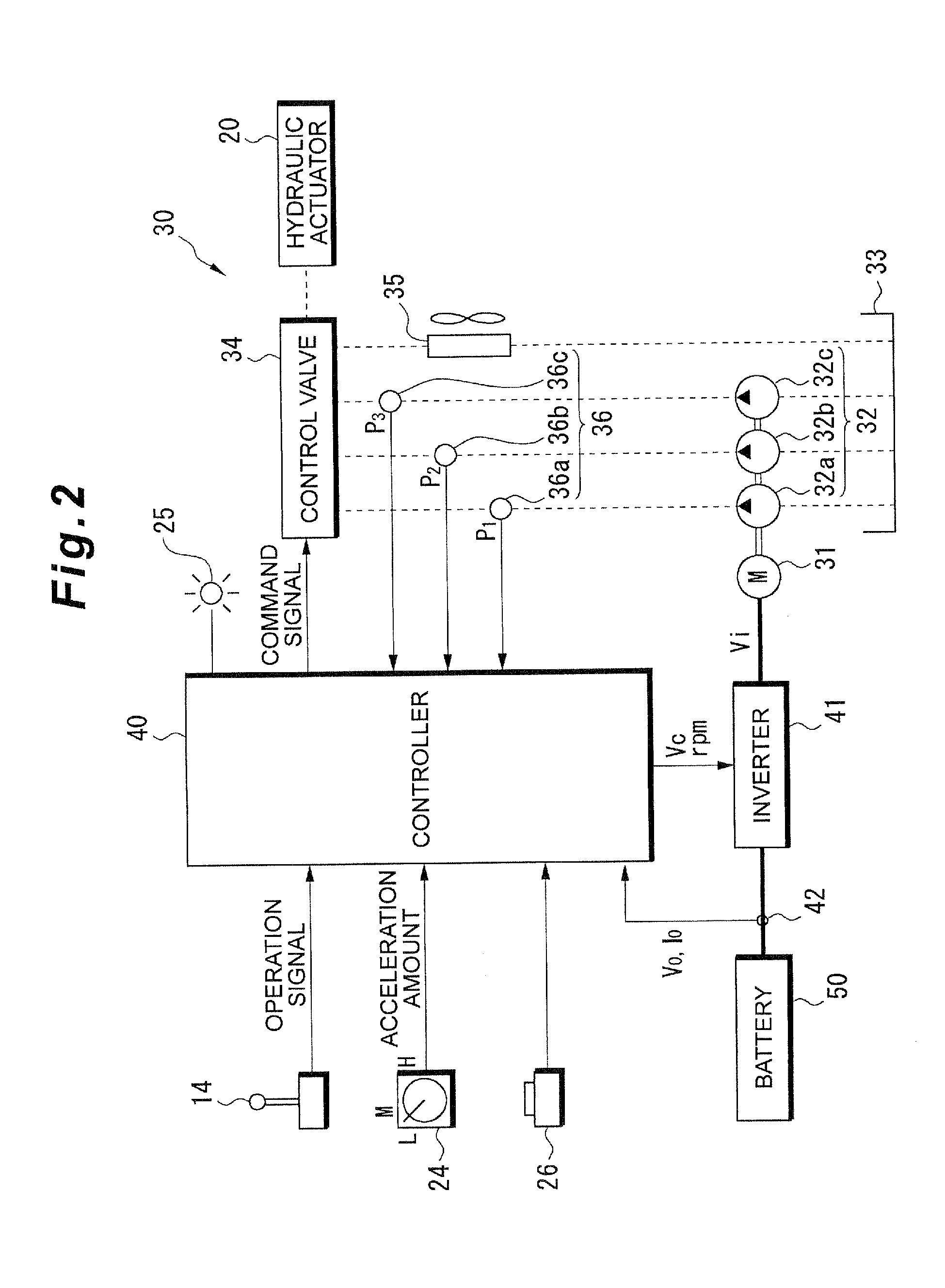
actuator, comprising: a hydraulic pump that supplies hydraulic oil to a hydraulic actuator; an electric motor that drives the hydraulic pump; a battery that supplies direct current electric power; an inverter that drives the electric motor by converting the direct current electric power of the battery to alternating current electric power and supplies the alternating current electric power to the electric motor; a controller that controls the operation of the electric motor by the inverter; and a current sensor (for example, the voltage or current sensor 42 in the embodiments) that measures the magnitude of the load current flowing from the battery to the inverter wherein the controller stops electric motor when the magnitude of the load current measured by the current sensor exceeds a predetermined threshold value for a predetermined continuous period of time.
[0008]When the working vehicle according to the present invention is constituted as described above, even if a large load is applied to the electric motor and the inverter heats due to excess current, before the protective circuit of the inverter operates, in other words, before the inverter reaches a high temperature state and stops, the operation of the electric motor is stopped by the controller, so it is possible to immediately restart work using the working vehicle, and work efficiency is improved.
[0009]In addition to the above constitution, the present invention further includes an electric motor relay (for example, the second relay 147 in the embodiments) that makes and breaks the connection between the battery (this is also called the main battery) and the inverter; a controller which is operated by direct current electric power from the main battery, and which controls the operation of the hydraulic actuator and the inverter, and makes and breaks the connection between the main battery and the inverter in use of the electric motor relay; a controller relay (for example, the first relay 146 in the embodiments) that makes and breaks the connection between the main battery and the controller; a power source monitoring controller that monitors the state of the main battery and that makes and breaks the connection between the main battery and the controller in use of the controller relay; a backup battery that supplies electric power to the power source monitoring controller; and a key switch that makes and breaks the connection between the power source monitoring controller and the backup battery. Then, in the working vehicle, configuration is employed to execute: when the power source monitoring controller and the backup battery are connected by the key switch and the power source monitoring controller is operating, a first step in which the power source monitoring controller obtains the state of the main battery and determines whether the main battery can be used or not; a second step in which the power source monitoring controller connects the main battery and the controller in use of the controller relay and starts up the controller when judgment is made in the first step that the main battery can be used; and a third step in which the controller starts the electric motor by connecting the inverter and the main battery in use of the electric motor relay.
[0010]Preferably this type of working vehicle according to the present invention has a protective circuit that obtains the status of the main battery, and in the first step, the power source monitoring controller supplies electric power to the protective circuit from the backup battery and starts up the protective circuit, and then obtains the status of the main battery from the protective circuit.
[0011]Also preferably this type of working vehicle according to the present invention has warning means (for example, the warning pilot lamp 152 in the embodiments) for warning that the main battery cannot be used, and in the first step, when determination is made that the main battery cannot be used, the power source monitoring controller issues a warning by the warning means.
[0012]Further, preferably this type of working vehicle according to the present invention has a DC-DC converter for converting the direct current voltage of the main battery to the voltage for operating the power source monitoring controller, and the controller relay connects the main battery and the controller and Connects the output of the DC-DC converter to the backup battery and the power source monitoring controller.

Problems solved by technology

However, in circumstances in which an engine cannot be used, such as in an underground construction site, construction machinery with an electric motor as the power source is used (see for example Japanese Patent Application Laid-open No. 2004-225355).

Method used


Image

  • Working vehicle
  • Working vehicle
  • Working vehicle

Examples


second embodiment

[0052]Next, a second embodiment will be explained with reference to FIGS. 10 through 12. The present embodiment is also applied to the crawler type power shovel 1 shown in FIG. 1, but to avoid duplication of explanation in the following, the same parts are given the same number and the same name, and their explanation has been omitted. Also, in FIG. 12, the symbol A enclosed in a circle after step S240 means move to connect to the symbol A enclosed within a circle immediately following the start.

[0053]The hydraulic unit 30 includes the electric motor 31, the hydraulic pump 32 that outputs hydraulic oil at a predetermined pressure and flow rate and that is driven by the electric motor 31, the tank 33 that stores hydraulic oil, the control valve (electromagnetic proportional valve) 34 that controls the supply of hydraulic oil output from the hydraulic pump 32 to the hydraulic actuator 20 in a supply direction and with a flow rate in accordance with its the manipulation of the operatin...


PUM


Abstract

A crawler type power shovel vehicle (1) operated by a hydraulic actuator (20), constructed from an electric motor (31) for driving a hydraulic pump (32) for supplying hydraulic oil to the hydraulic actuator (20), a battery (50) for supplying direct current power, an inverter (41) for operating the electric motor (31) by converting the direct current power into alternating current power and supplying it to the motor, a controller (40) for causing the inverter (41) to control operation of the electric motor (31), and a voltage / current sensor (42) for detecting the magnitude of a load current flowing from the battery (50) into the inverter (41). The controller (40) stops the motor (31) when the magnitude of the load current detected by the voltage / current sensor (42) continuously exceeds a predetermined threshold for a predetermined time period.

Description

TECHNICAL FIELD[0001]The present invention relates to a working vehicle having an electric motor driven by a battery as the drive power source, and more particularly relates to a working vehicle that operates by hydraulic oil supplied by a hydraulic pump driven by the electric motor.TECHNICAL BACKGROUND[0002]In conventional working vehicles the drive power source is normally an engine. However, in circumstances in which an engine cannot be used, such as in an underground construction site, construction machinery with an electric motor as the power source is used (see for example Japanese Patent Application Laid-open No. 2004-225355). The power sources for these electric motors are a commercial power supply, or batteries on the construction machinery that are charged from a commercial power supply. Also, the operation of this type of electric motor is controlled using an inverter.DISCLOSURE OF THE INVENTIONProblems to be Solved by the Invention[0003]However, when a load is applied to...

Claims


Application Information

Patent Timeline
IPC IPC(8): H02H7/18H02H7/085
CPCB60L11/18E02F9/207E02F9/2292H02P27/06E02F9/267Y02T10/642Y02T10/7005E02F9/2091E02F9/2095H02P29/021B60L3/003B60L3/0046B60L3/04B60L2200/40B60L2240/529B60L50/15E02F9/2246H02P29/0241Y02T10/64Y02T10/70Y02T10/7072
Inventor YOSHIOKA, MASAO
Owner TAKEUCHI SEISAKUSHOKK
Features
  • Generate Ideas
  • Intellectual Property
  • Life Sciences
  • Materials
  • Tech Scout
  • Unparalleled Data Quality
  • Higher Quality Content
  • 60% Fewer Hallucinations
Learn More