Imaging system, camera body and interchangeable lens

a technology of interchangeable lenses and imaging systems, applied in the field of imaging systems, can solve the problems of not being applicable to imaging systems including interchangeable lenses and camera bodies, not being able to transmit a wobbling control signal from the camera body to the interchangeable lens, etc., and achieve the effect of high precision and high accuracy automatic focus control

Active Publication Date: 2009-10-22
PANASONIC CORP
View PDF11 Cites 23 Cited by
  • Summary
  • Abstract
  • Description
  • Claims
  • Application Information

AI Technical Summary

Benefits of technology

[0010]In accordance with the aforementioned arrangement, the camera body transmits a reference signal and information indicating a delay time relative to the reference signal to an interchangeable lens, and based on the reference signal and the information indicating the delay time thus received, the interchangeable lens drive-controls the focus lens. For this reason, the exposure timing of a desired area of the imaging element can be made virtually coincident with the timing of a stop period of the wobbling operation of the focus lens so that it is possible to carry out auto-focus control with high precision. Moreover, by transmitting the reference signal from the camera body to the interchangeable lens during a period in which no communication process is performed between the interchangeable lens and the camera body, it enables control of the focus lens to be driven at a desired timing, without any waiting time for communication process, thus providing high accuracy automatic focus control.it

Problems solved by technology

However, in the imaging system including an interchangeable lens and a camera body, communication between the interchangeable lens and the camera body is made periodically, and thus it is not possible to transmit a wobbling control signal from the camera body to the interchangeable lens at a desired timing.
For this reason, the technology described in JP-A-2006-047954 is not applicable to the imaging system including an interchangeable lens and a camera body.

Method used


Image

  • Imaging system, camera body and interchangeable lens
  • Imaging system, camera body and interchangeable lens
  • Imaging system, camera body and interchangeable lens

Examples


first embodiment

1. Structure

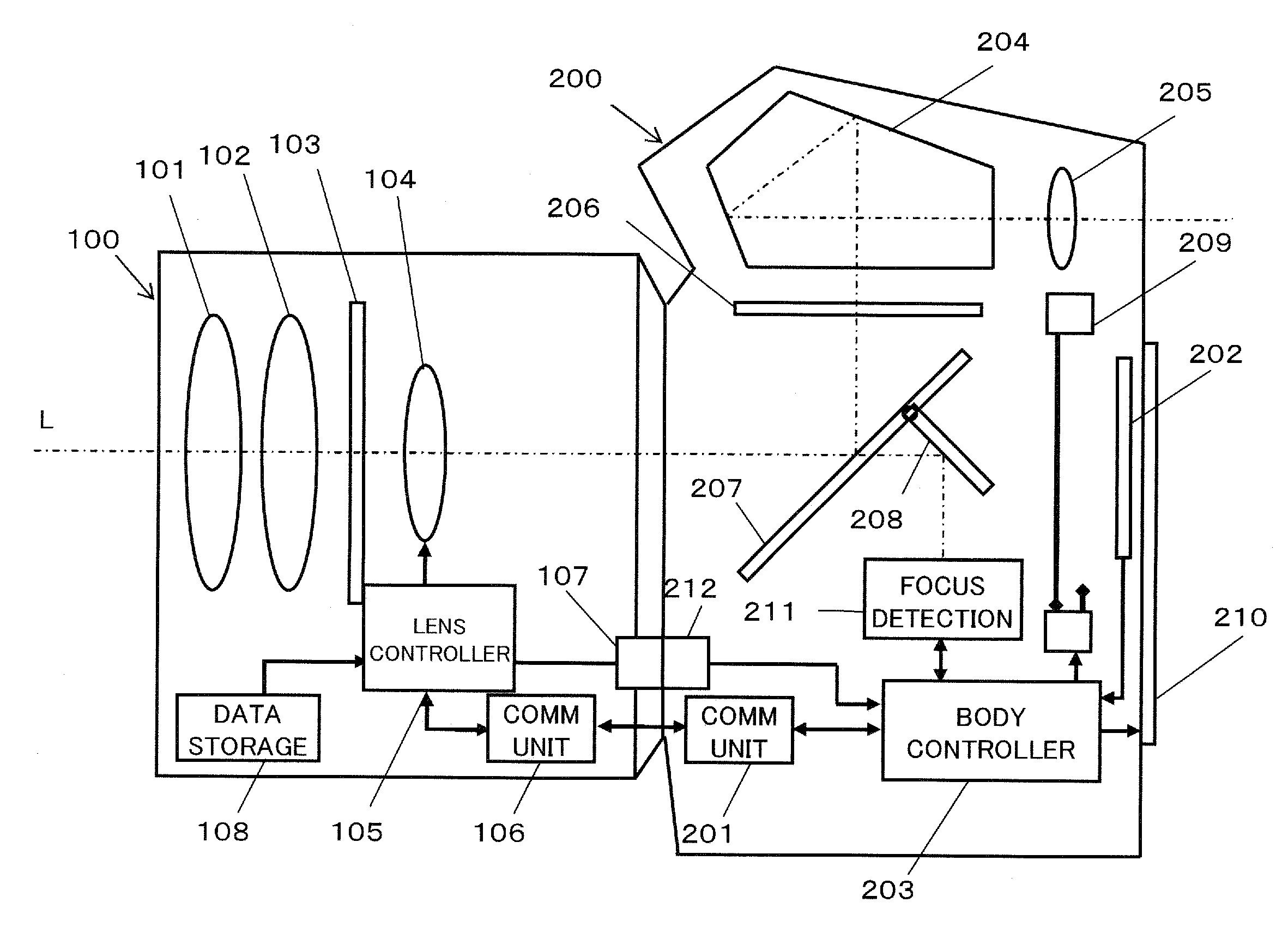
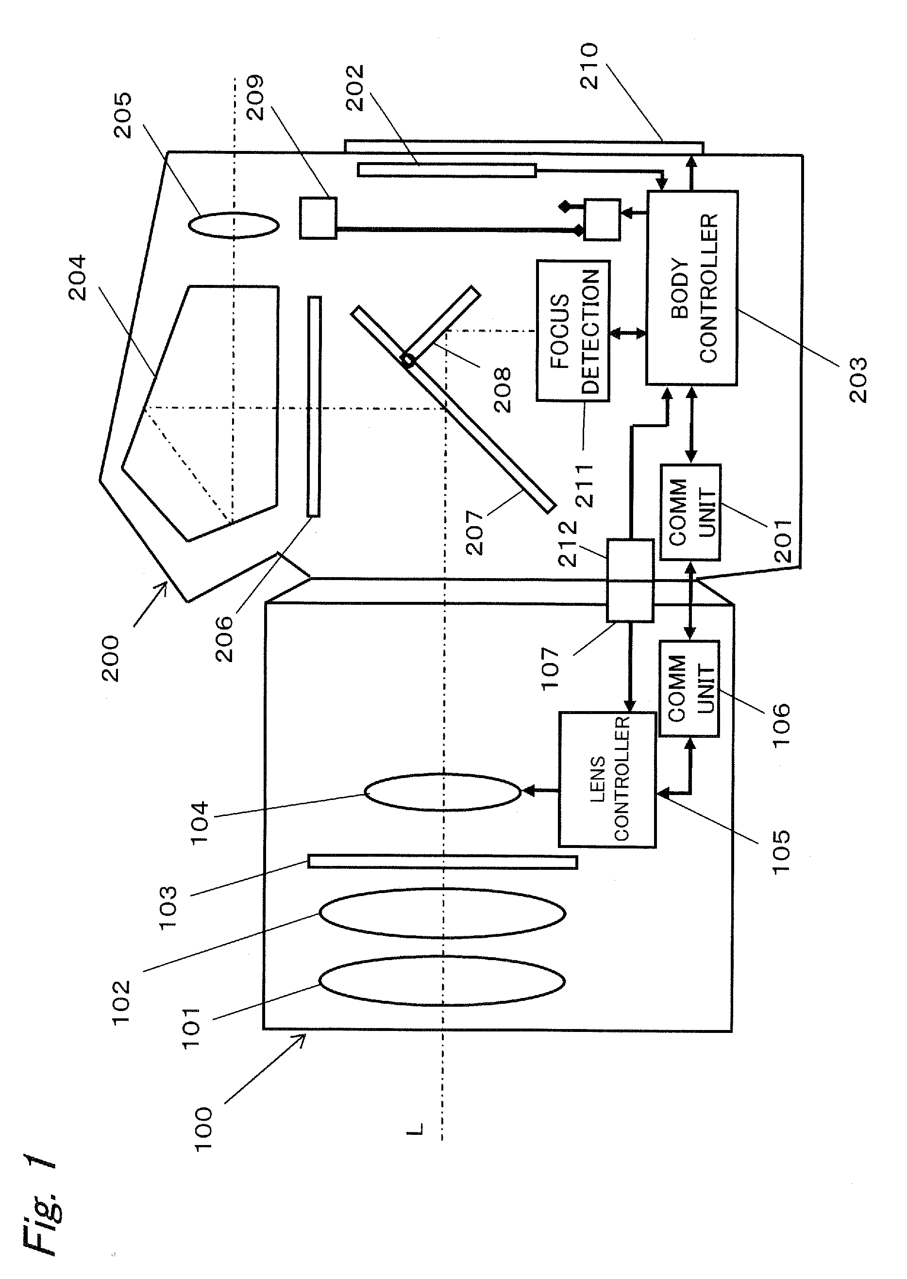
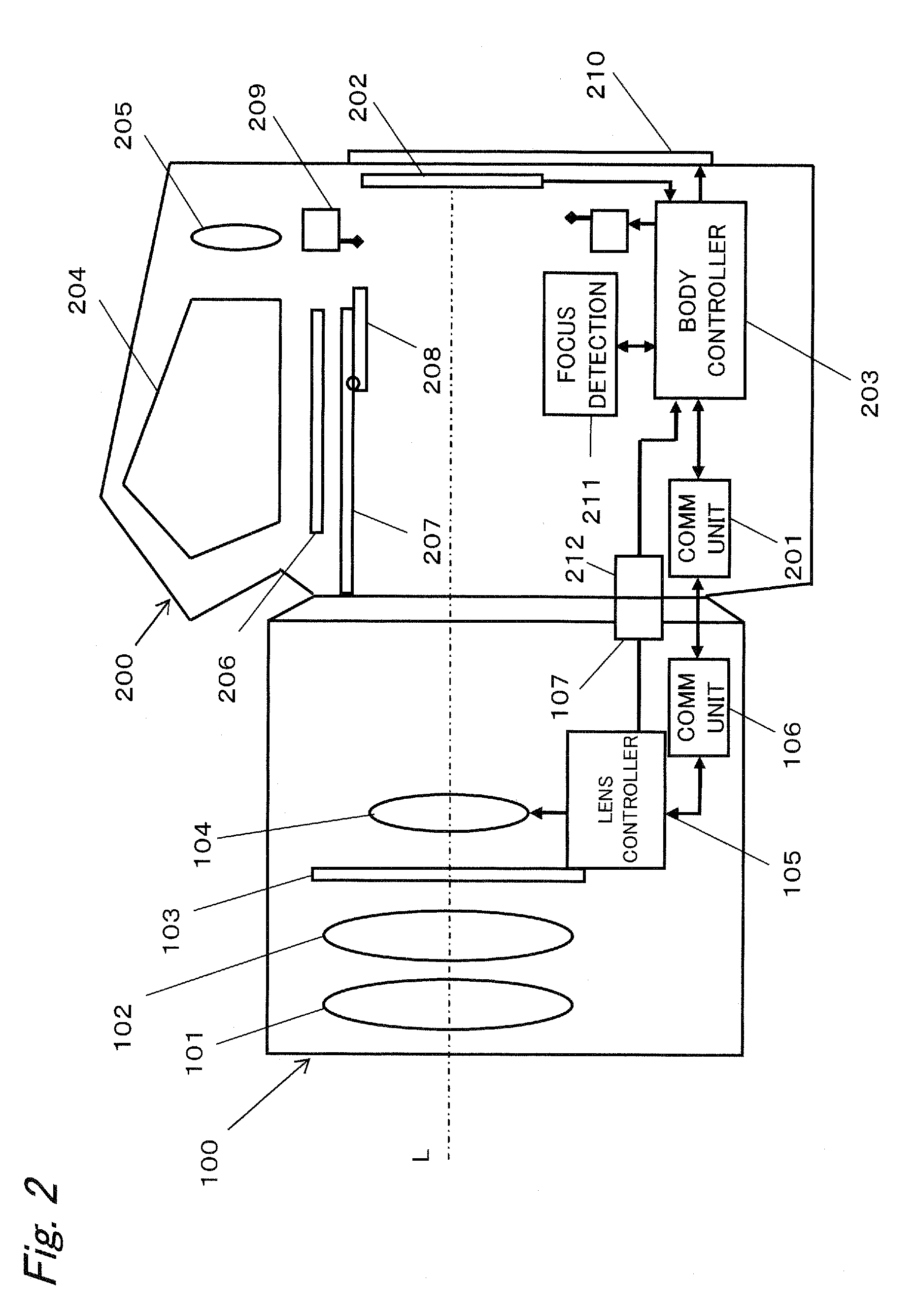
[0024]FIGS. 1 and 2 are block diagrams that show an imaging system in accordance with a first embodiment. FIGS. 1 and 2 respectively show structures of the imaging system in a finder view mode and in a live view mode respectively (each mode will be detailed later). The imaging system is composed of an interchangeable lens 100 and a camera body 200. The interchangeable lens 100 is mountable to the camera body 200 at a predetermined position.

1-1. Camera Body

[0025]The camera body 200 is provided with a second communication unit 201, an imaging element 202, a main body controller 203, a penta-prism 204, an eyepiece lens 205, a focus plate 206, a main mirror 207, a sub mirror 208, a shutter 209, an image display-use liquid crystal display unit (hereinafter, referred to as “LCD”) 210, a focus detection unit 211, and a second terminal 212.

[0026]The main body controller 203 is an LSI which integrates a microcomputer, a control circuit for controlling respective parts in the came...

second embodiment

[0093]In the first embodiment, no limitations are particularly provided to the delay time (information indicating a phase relating to a reference signal) which is transmitted to the lens controller 105 from the main body controller 203. However, when the delay time to a reference signal is too short or too long, the lens controller 105 sometimes may fail to normally control the operation of the focus lens 104. The present embodiment provides an imaging system capable of solving such a problem.

[0094]FIG. 13 is a block diagram that shows an imaging system in accordance with a second embodiment. This structure differs from the structure of the imaging system of the first embodiment shown in FIG. 1 in that the interchangeable lens 100 has a storage unit 108. The other structures are the same as those of FIG. 1. The imaging system of the second embodiment is also provided with a finder view mode and a live view mode.

[0095]The storage unit 108 is means for storing characteristic informati...


PUM


Abstract

An imaging system includes an interchangeable lens and a camera body. The camera body includes a main body controller operable to transmit a reference signal for providing a reference of a driving start timing of the focus lens and delay time information indicating delay time with respect to the reference signal, to the interchangeable lens. The interchangeable lens includes a lens controller operable to control the focus lens to be driven at a timing obtained by delaying the timing provided by the reference signal by the delay time based on the reference signal and the delay time information received from the main body controller. The delay time is set so that, for example, an exposure timing of a predetermined area in the imaging element is substantially coincident with a stop period of the wobbling operation of the focus lens.

Description

BACKGROUND[0001]1. Technical Field[0002]The technical field relates to an imaging system including an interchangeable lens and a camera body, and a camera body and an interchangeable lens used for the imaging system, and in particular relates to a driving control operation of a focus lens included in the interchangeable lens.[0003]2. Related Art[0004]JP-A-2006-047954 has disclosed a technology relating to an auto-focus method used for carrying out high-speed auto-focus control with high precision. In accordance with the method disclosed by JP-A-2006-047954, a wobbling controller generates a wobbling control signal in such a manner that a timing of a period in which central pixels in a predetermined area of an image are exposed is coincident with the center timing between a period in which the wobbling operation is stopped on the near side and a period in which the wobbling operation is stopped on the far side. With this arrangement, the relationship between the timing of the wobblin...

Claims


Application Information

Patent Timeline
Patent Type & Authority Applications(United States)
IPC IPC(8): H04N5/232
CPCG03B13/36G03B17/14H04N5/23212H04N5/23209G03B19/12H04N23/663H04N23/672H04N23/673H04N23/61H04N23/635
Inventor KAWAZOE, KENJIOKAMOTO, MITSUYOSHIKITAHIRA, NAOTAKESHIBUNO, KOJI
Owner PANASONIC CORP
Why Eureka
Try Eureka