Magnetic sensor and magnetic encoder using same

Inactive Publication Date: 2009-10-22
ALPS ALPINE CO LTD
View PDF0 Cites 18 Cited by
  • Summary
  • Abstract
  • Description
  • Claims
  • Application Information

AI Technical Summary

Benefits of technology

[0014]Furthermore, since a soft magnetic material element is provided on a side of the magneto-resistance effect element with a space between the soft magnetic material element and the magneto-resistance effect element, the external magnetic field (sensing magnetic field) can be pulled in the direction of the substrate, in which the magneto-resistance effect element is provided. Thus, it is possible to, compared with the related art, amplify an external magnetic field applied to the magneto-resistance effect element. As a result, even if a bias magnetic field Hin is applied to the free magnetic layer, it is possible to improve magnetic detection sensitivity, compared with the related art, making it possible to increase the output.
[0015]The soft magnetic material elements are arranged on both sides of the magneto-resistance effect elements with a spacing therebetween. This makes it possible to effectively amplify an external magnetic field applied to the magneto-resistance effect element, which is preferable.
[0016]Preferably, a plurality of the magneto-resistance effect elements are arranged on the substrate, and the soft magnetic material element is arranged between the sides of magneto-resistance effect elements and on the outer side of each of the magneto-resistance effect elements arranged on both sides of the arrangement. This makes it possible to amplify the external magnetic field applied to each magneto-resistance effect element.
[0017]Furthermore, preferably, the volume of each of the soft magnetic material elements provided on the outermost sides is larger than the volume of each of the soft magnetic material elements arranged on an inner side. For example, preferably,

Problems solved by technology

As a result, a problem of the o

Method used


Image

  • Magnetic sensor and magnetic encoder using same
  • Magnetic sensor and magnetic encoder using same
  • Magnetic sensor and magnetic encoder using same

Examples


Embodiment Construction

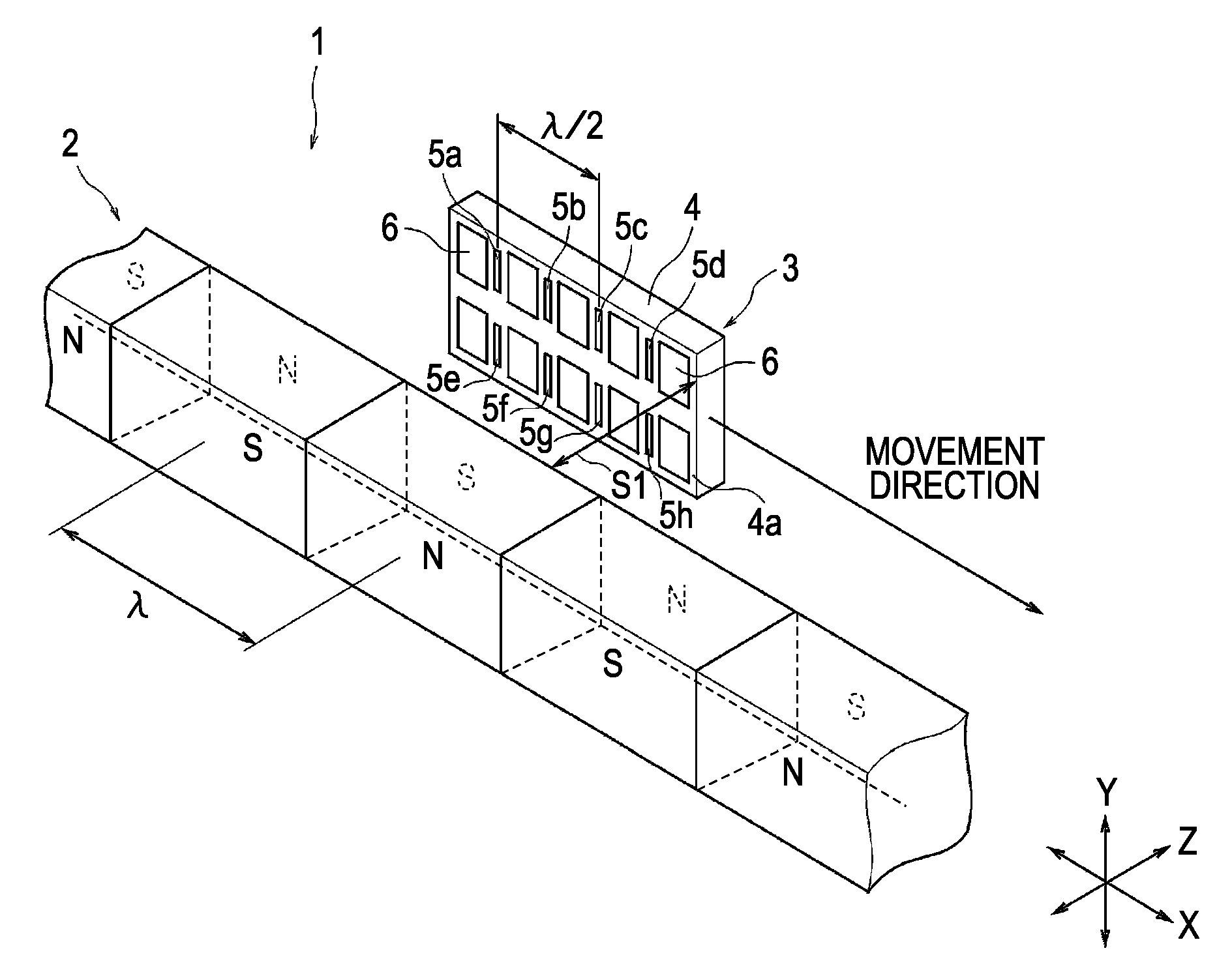
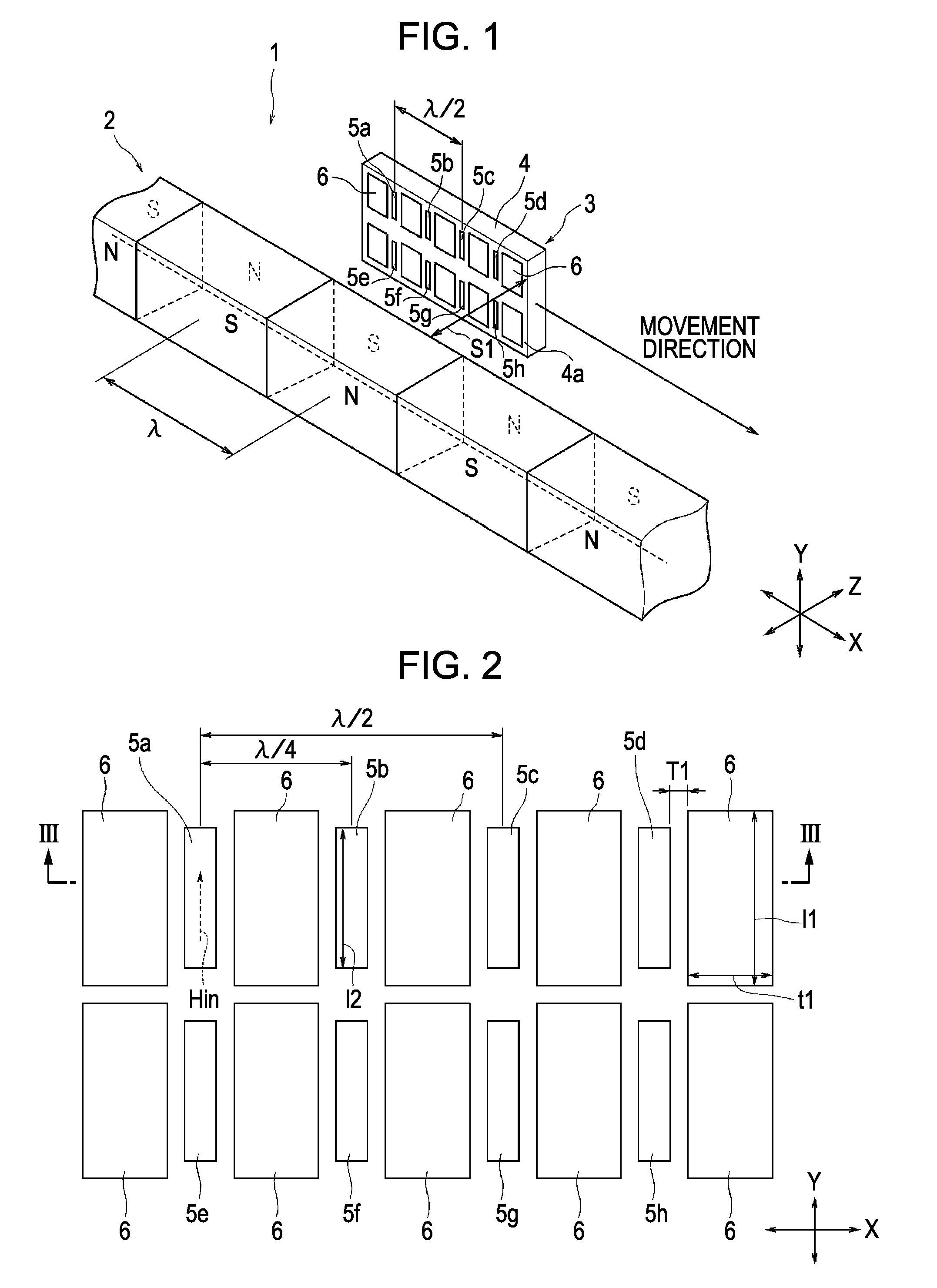
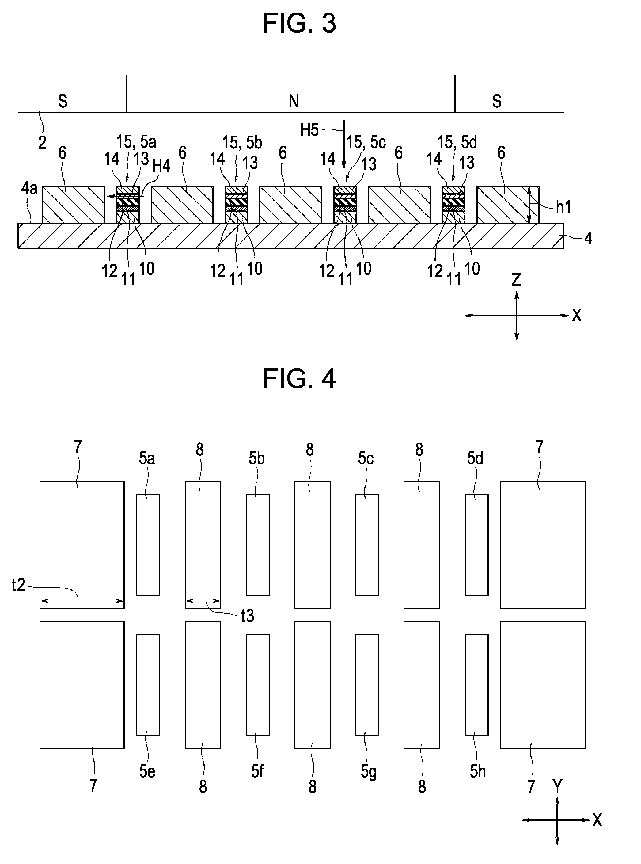
[0029]FIG. 1 is a partial perspective view of a magnetic encoder according to the present embodiment. FIG. 2 is an enlarged plan view of a magnetic sensor, which illustrates the arrangement of magneto-resistance effect elements and soft magnetic material elements on a substrate. FIG. 3 is an enlarged sectional view of the magnetic sensor when cut along the A-A line shown in FIG. 2 in the direction of the film thickness and viewed from the arrow direction, and a partially enlarged side view of a magnet opposing the magnetic sensor. FIG. 4 is an enlarged plan view of a magnetic sensor showing a modification of FIG. 2. FIG. 5 is an enlarged plan view of a magnetic sensor showing a modification of FIG. 2. FIG. 6 is an enlarged sectional view of a magnetic sensor showing a modification of FIG. 3. FIG. 7 includes circuit diagrams of a magnetic sensor. FIG. 8 is a graph showing an R-H curve of a magneto-resistance effect element.

[0030]The directions among the X direction, the Y direction, ...


PUM


Abstract

Soft magnetic material elements are provided on both sides of each of magneto-resistance effect elements with a spacing therebetween. As a result, an external magnetic field generated from a magnet can be pulled to above a substrate on which the magneto-resistance effect element is provided, thereby making it possible to amplify the external magnetic field to be applied to the magneto-resistance effect element to more than in the related art. Since a bias magnetic field is applied to a free magnetic layer, a magnetic sensor is resistant to a disturbance magnetic field. Moreover, since the external magnetic field applied to the magneto-resistance effect element can be amplified, even if the bias magnetic field is applied to the free magnetic layer, the magnetic detection sensitivity can be apparently improved to more than in the related art, thereby increasing the output.

Description

CLAIM OF PRIORITY[0001]This application is a Continuation of International Application No. PCT / JP2007 / 073823 filed on Dec. 11, 2007, which claims benefit of the Japanese Patent Application No. 2006-335703 filed on Dec. 13, 2006, which are hereby incorporated by reference.BACKGROUND OF THE INVENTION[0002]1. Field of the Invention[0003]The present invention relates to a magnetic sensor that is, in particular, resistant to a disturbance magnetic field and that is capable of amplifying an external magnetic field (sensing magnetic field) applied to a magneto-resistance effect element, and a magnetic encoder using the magnetic sensor.[0004]2. Description of the Related Art[0005]Magneto-resistance effect elements (GMR elements) using a giant magneto-resistance effect (GMR effect) have been in demand as magnetic heads incorporated in a hard disk device, disclosed in Japanese Unexamined Patent Application Publication No. 2002-232037.[0006]The basic film structure of the GMR element is formed...

Claims


Application Information

Patent Timeline
IPC IPC(8): G11B5/33
CPCB82Y25/00G01R33/093G01D5/145
Inventor KURATA, KOJITOKUNAGA, ICHIRO
Owner ALPS ALPINE CO LTD
Why Eureka
Try Eureka