Lighting apparatus

a technology of light fittings and light fittings, which is applied in the direction of mass transit vehicle lighting, lighting and heating apparatus, lighting support devices, etc., can solve the problems of difficult to smoothly start the rotation of the same without harsh frictional noise, difficult to smoothly change the orientation of the light fitting, and gradual wear of metal coatings, etc., to achieve easy to change the orientation, maintain the operability of the light fitting, and good heat dissipation performan

Inactive Publication Date: 2009-10-22
TOSHIBA LIGHTING & TECH CORP +1
View PDF5 Cites 15 Cited by
  • Summary
  • Abstract
  • Description
  • Claims
  • Application Information

AI Technical Summary

Benefits of technology

[0012]It is an object of the preset invention to provide a lighting apparatus having good heat dissipation performance, and capable of maintaining, o

Problems solved by technology

However, the metal coating is gradually worn away while the orientation of the light fitting is repeatedly changed.
At this time, galling of the ground layers occurs to degrade the sliding performance, with the result that it becomes difficult to smoothly change the orientation of the light fitting.
Therefore, when the light fitting is in a static condition, it is hard to smoothly start the

Method used


Image

  • Lighting apparatus
  • Lighting apparatus
  • Lighting apparatus

Examples


Embodiment Construction

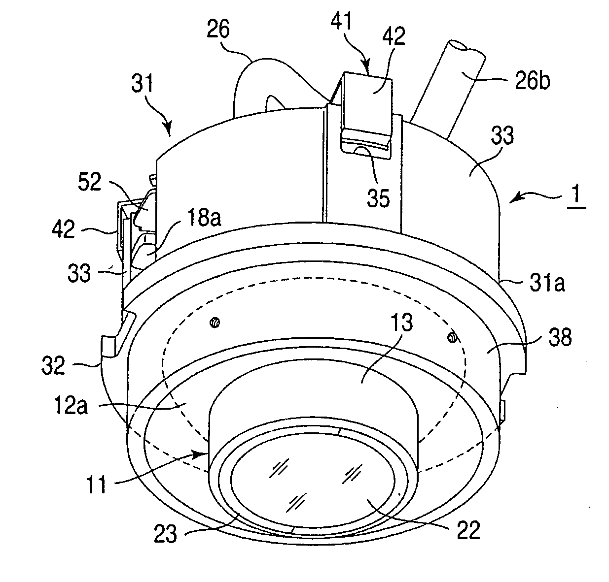
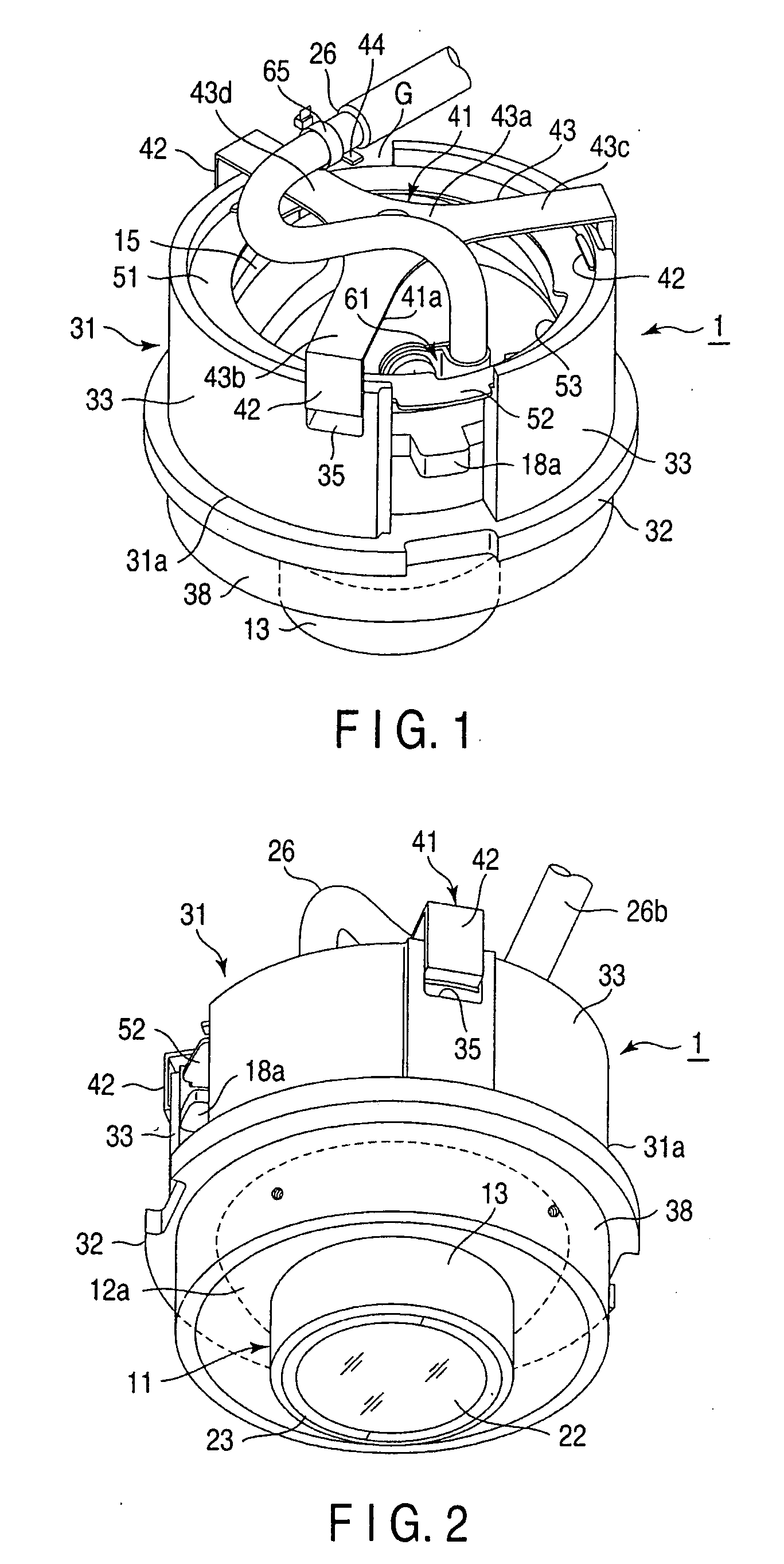
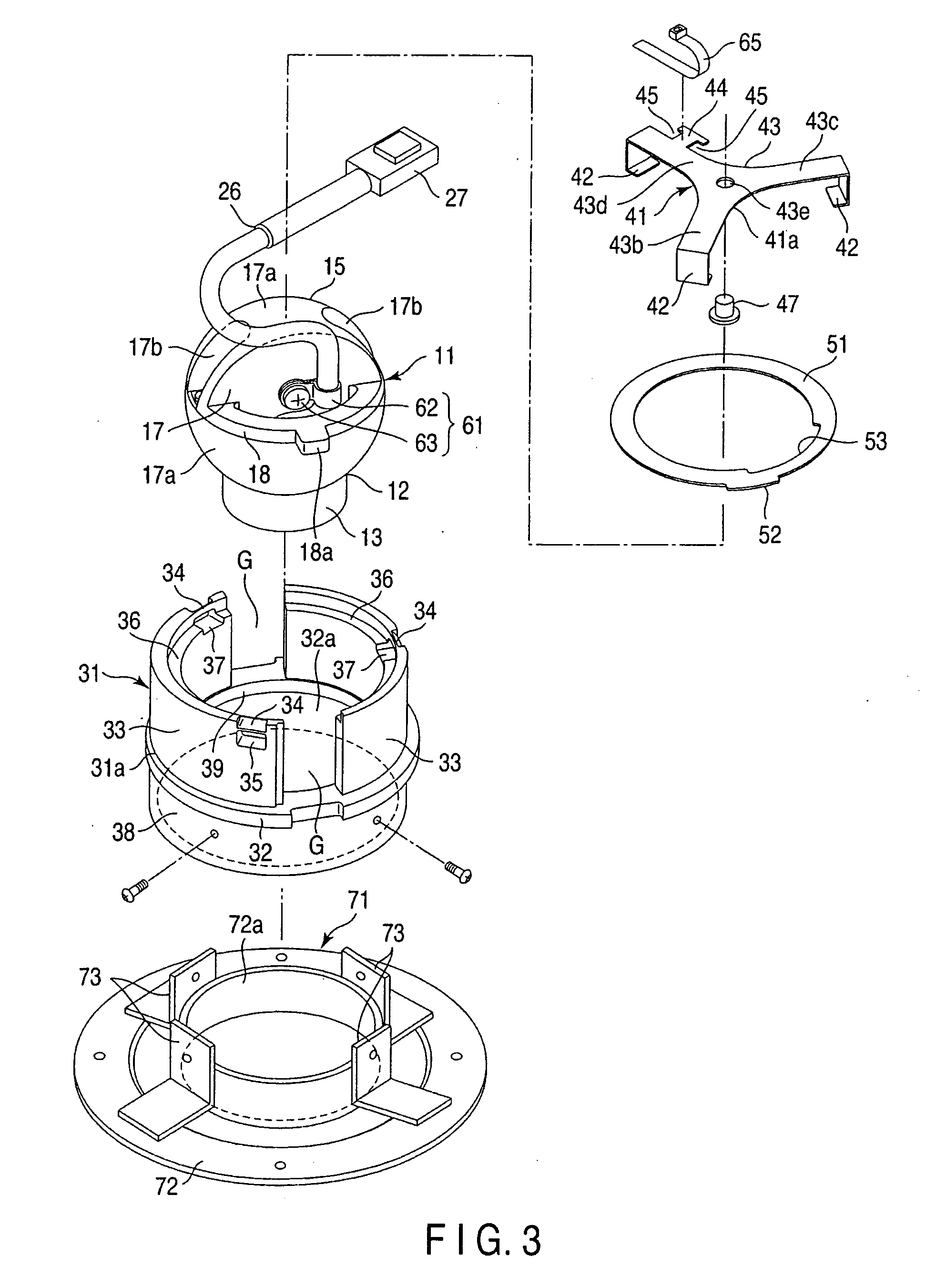
[0029]Referring to FIGS. 1 to 6, a reading light 1 as a lighting apparatus according to an embodiment of the invention will be described.

[0030]FIG. 1 is a perspective view illustrating the structure of the rear portion of the reading light 1, FIG. 2 is a perspective view illustrating the structure of the front portion of the reading light 1, and FIG. 3 is an exploded perspective view illustrating the reading light 1. Further, FIG. 4 is a sectional view taken along the axis of the reading light 1, FIG. 5 is a sectional view taken along line V-V of FIG. 4, and

[0031]FIG. 6 is an exploded sectional view illustrating the reading light 1.

[0032]The reading light 1 is attached to a seat in passenger transportation means, such as railroad wagons, airplanes and ships, or provided near the seat. The reading light 1 is used to apply spot light to a position near a user, and has a structure for slightly changing the angle of the spot light.

[0033]As shown in FIGS. 4 and 5, an attachment member A ...


PUM


Abstract

A reading light incorporates a light fitting containing a light source, a light main body and a spring. The cover of the light fitting includes an outer surface formed of a part of a spherical surface. The body of the light fitting is formed of a metal, and includes a back surface formed of another part of the spherical surface. The light main body includes a receiving/guiding portion that supports the outer surface. The receiving/guiding portion supports the light fitting so that the light fitting is rotatable, thereby enabling the direction of light emitted from the light fitting to be changed. The light fitting is fitted in the light main body by pressing the back surface using the spring. Either the receiving/guiding portion or cover is formed of a metal, and the other is formed of a resin.

Description

CROSS-REFERENCE TO RELATED APPLICATIONS[0001]This application is based upon and claims the benefit of priority from prior Japanese Patent Applications No. 2008-109445, filed Apr. 18, 2008; and No. 2009-064937, filed Mar. 17, 2009, the entire contents of both of which are incorporated herein by reference.BACKGROUND OF THE INVENTION[0002]1. Field of the Invention[0003]The present invention relates to a lighting apparatus capable of changing its light emission direction, and more specifically, a lighting apparatus, such as a reading light, attached to, for example, a seat in transportation means, such as railroad wagons, airplanes and ships.[0004]2. Description of the Related Art[0005]As a lighting apparatus of this type, a down light is known in which, for example, a light fitting of a substantially spherical shape is rotatably held by a substantially cylindrical light main body, thereby enabling the direction of light emission to be changed (see, for example, Jpn. Pat. Appln. KOKAI P...

Claims


Application Information

Patent Timeline
IPC IPC(8): F21V21/18
CPCB64D2011/0053B60Q3/0253B60Q3/44
Inventor ONO, KEISUKE
Owner TOSHIBA LIGHTING & TECH CORP
Why Eureka
Try Eureka