Plate material conveying device

a technology of conveying device and plate material, which is applied in the direction of thin material handling, article separation, gripping head, etc., can solve the problems that the suction type holders may not hold the remainder of materials, and achieve the effect of reducing time required, efficient conveying, and increasing the speed of plate material conveying

Inactive Publication Date: 2009-10-22
MURATA MASCH LTD
View PDF8 Cites 22 Cited by
  • Summary
  • Abstract
  • Description
  • Claims
  • Application Information

AI Technical Summary

Benefits of technology

[0007]An object of the present invention is to solve the above-described problems and to provide a plate material conveying device including a compact traveling member to enable an increase in plate material conveyance speed and a reduction in time required for acceleration and deceleration, and to allow small plate materials to be more efficiently conveyed, and also the plate material conveying device enable one of a gripper and a suction type plate material holder to be selected for conveyance of a plate material.
[0008]Another object of the present invention is to enable remainder materials with the inside thereof cut out to be conveyed and to allow the conveyed remainder materials to be smoothly stacked in a remainder material yard.
[0009]Yet another object of the present invention is to enable the remainder materials or the like to be stably conveyed even if the remainder materials are large in size.

Problems solved by technology

Furthermore, when remainder materials resulting from cutting-out of workpieces from raw plate materials are carried out, suction type holders may fail to hold the remainder materials.

Method used


Image

  • Plate material conveying device
  • Plate material conveying device
  • Plate material conveying device

Examples


Embodiment Construction

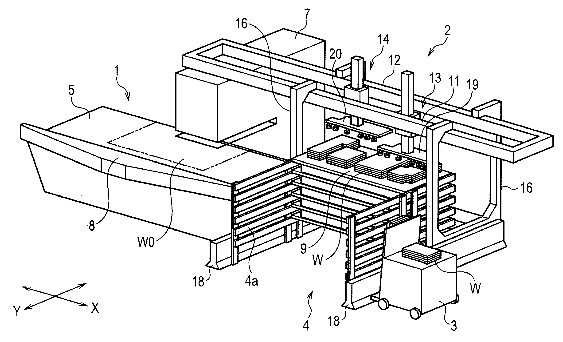
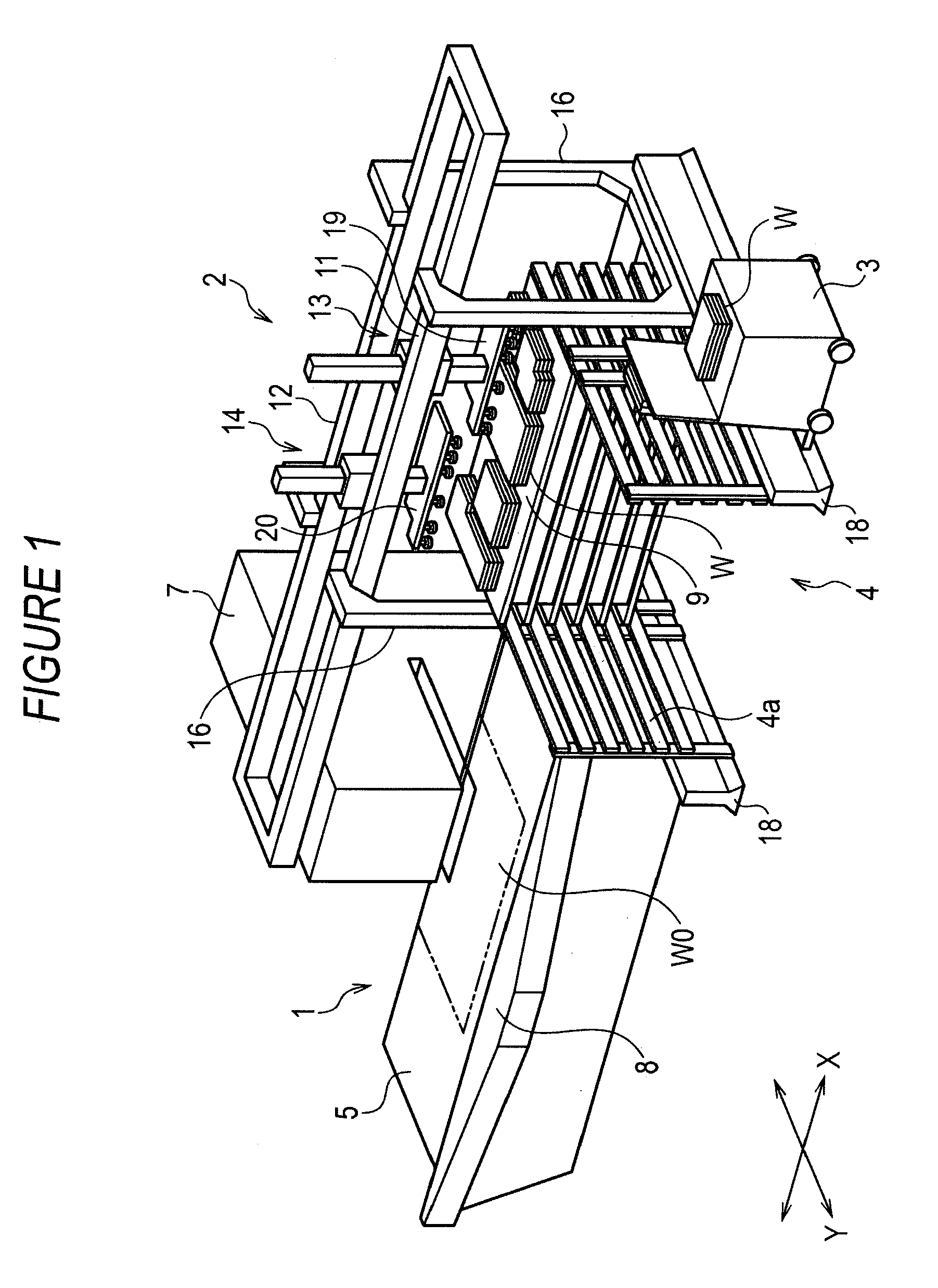
[0034]An embodiment of the present invention will be described with reference to FIGS. 1 to 13. FIG. 1 is a perspective view of a plate material processing system as a whole including a plate material processing machine 1, a plate material conveying device 2, a pallet 9 and a plate material transport vehicle 3 both serving as a plate material placement portion, and a plate material stocker 4. The plate material processing system further includes a plate material carry-in device (not shown in the drawings) that carries a raw plate material W0 into the plate material processing machine 1. However, description of the plate material carry-in device is omitted. The plate material processing machine 1 and the plate material conveying device 2 are controlled by a computerized processor control device and a computerized conveyance control device (not shown in the drawings), respectively, according to respective control programs.

[0035]The plate material processing machine 1 provides the func...


PUM

PropertyMeasurementUnit
sizeaaaaaaaaaa
shapeaaaaaaaaaa
weightaaaaaaaaaa

Abstract

The present invention provides a plate material conveying device including a compact traveling member to enable an increase in plate material conveyance speed and a reduction in time required for acceleration and deceleration and to allow small plate materials to be more efficiently conveyed, the plate material conveying device further enabling one of a gripper and a suction type plate material holder to be selected for conveyance of a plate material. Traveling members 13, 14 are provided on respective tracks 11, 12 so as to travel freely along the respective tracks 11, 12. Each of the traveling members 13, 14 has a plate material holder support frame 21, 22 supporting suction type plate material holders 23A, 23B, 23C. The plate material holder support frame 21, 22 has a frame main body 21a, 22a, and a turning frame 21b, 22b which is turnable in a substantially horizontal direction with respect to the frame main body 21a, 22a and which is turnable to a position where the supported plate material planarly overlaps the adjacent track. Each of the turning frames 21b, 22b has a gripper 60 gripping an end of the plate material. An opening of the gripper is configured to face a central side of the plate material.

Description

FIELD OF THE INVENTION[0001]The present invention relates to a plate material conveying device that carries raw plate materials into a plate material processing machine and carries out product plate materials processed by the plate material processing machine as well as remainder materials.BACKGROUND OF THE INVENTION[0002]In a plate material conveying device of this kind, a plurality of plate material holders are provided on a traveling member traveling along a predetermined track, to hold and covey plate materials (for example, the Unexamined Japanese Patent Application Publication (Tokkai) No. 2000-351032). The plate material holders are composed of, for example, suction pads and can hold and release a plate material. In general, the plate material holders are arranged so as to cover the largest one of the plate materials to be conveyed. A special plate material conveying device is described in the Unexamined Japanese Patent Application Publication (Tokkai) No. 2000-117373. The pl...

Claims


Application Information

Patent Timeline
Patent Type & Authority Applications(United States)
IPC IPC(8): B65H29/24
CPCB26D7/0633B65H29/241B65H35/00B65H2301/4212B65H2301/42172B65H2555/30B65H2406/342B65H2220/09B65H2405/581B65H2405/51B25J9/0087B25J9/026B25J15/0061B25J15/0616
Inventor KATSUYAMA, DAISUKE
Owner MURATA MASCH LTD
Why Eureka
Try Eureka