

Wind generator blade with divergent trailing edge
a wind turbine blade and trailing edge technology, which is applied in the direction of liquid fuel engines, vessel construction, marine propulsion, etc., can solve the problems of increased drag and reduced lift, negative drag effect, extra drag, etc., to improve the leading edge roughness sensitivity, increase the functional reliability of the blade, and reduce the uncertainty in loads and aerodynamic efficiency
- Summary
- Abstract
- Description
- Claims
- Application Information
AI Technical Summary
Benefits of technology
Problems solved by technology
Method used
Image

Examples
Embodiment Construction
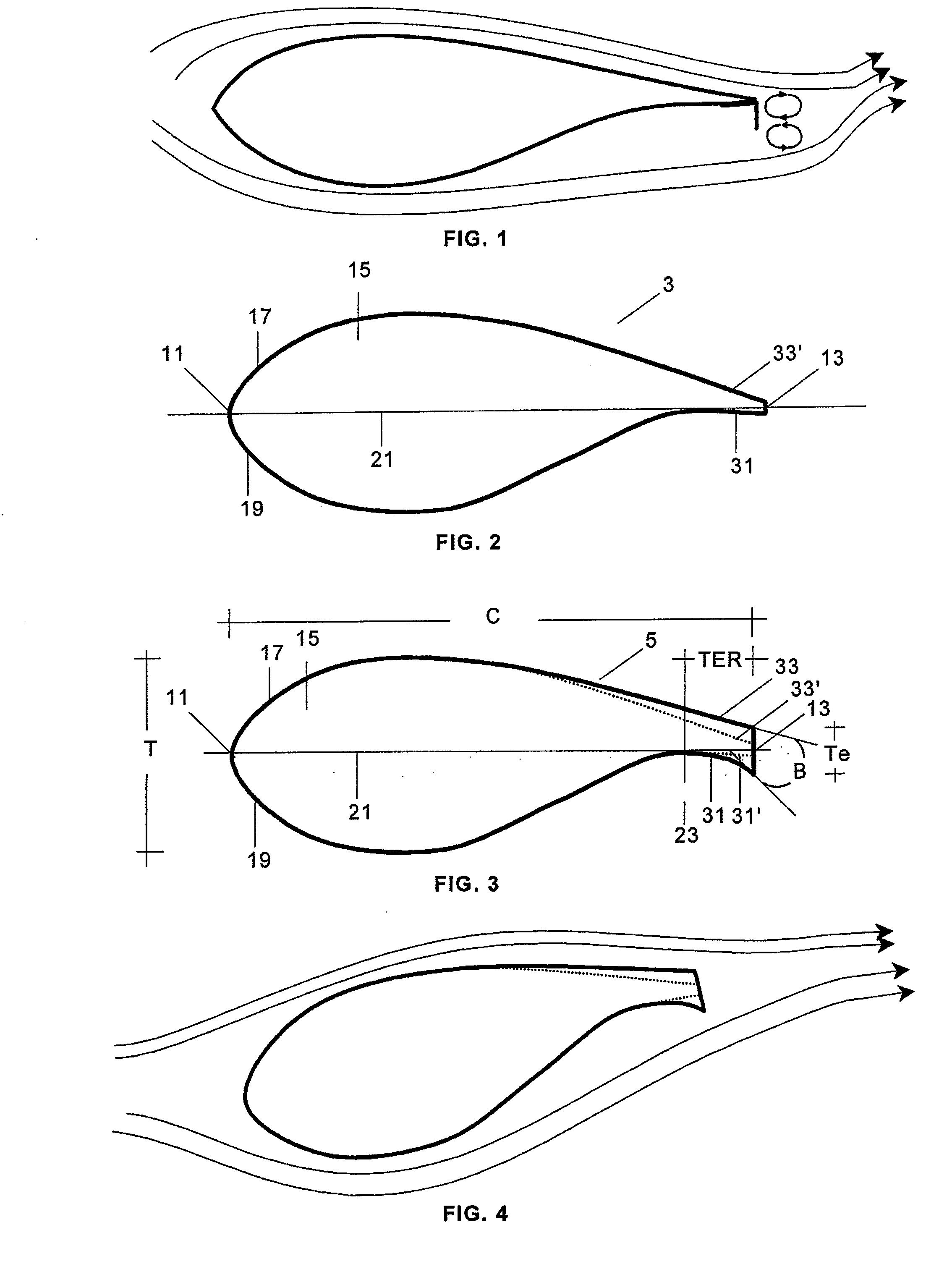
[0020]FIG. 2 shows a known standard profile 3 of a wind turbine blade having a leading edge 11, a moderately blunt trailing edge 13 and a lifting surface 15 with a suction side 17 and a pressure side 19. The chord 21 is an imaginary line drawn between the leading edge 11 and the trailing edge 13.
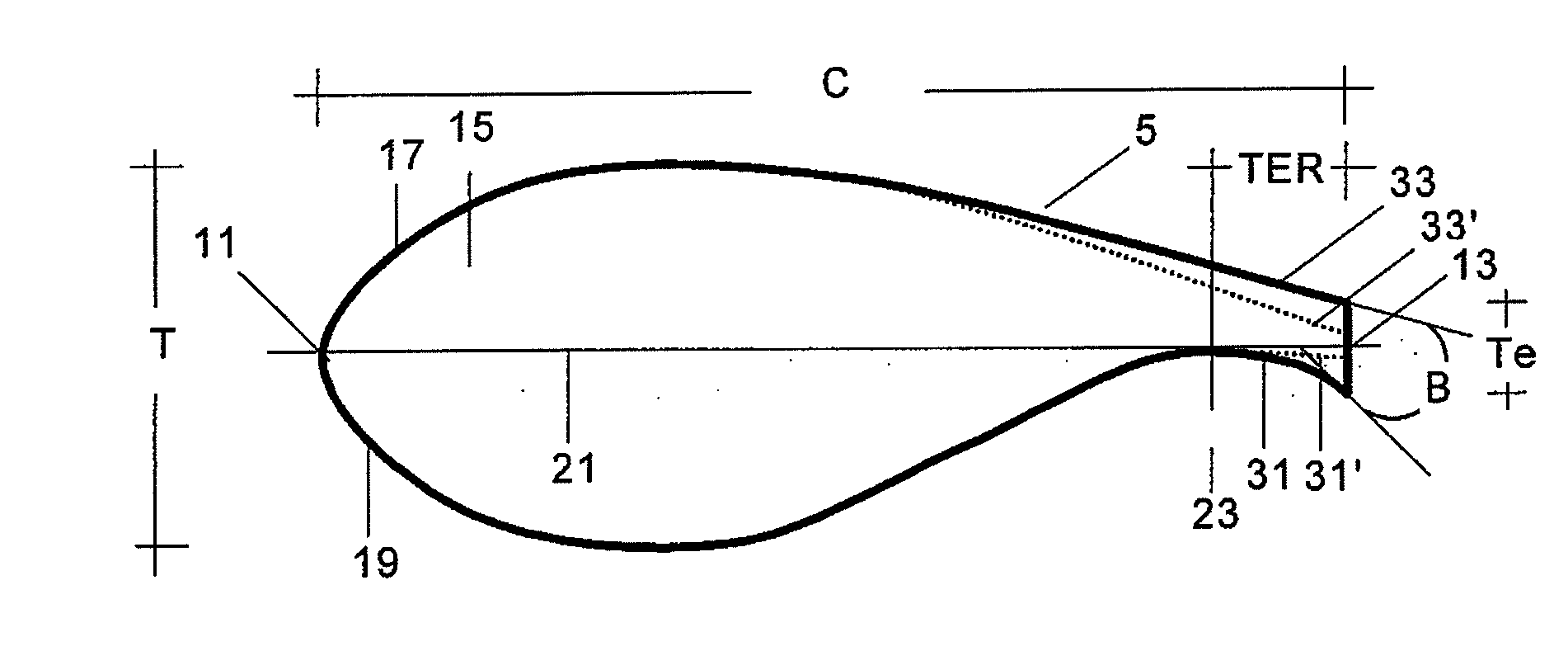
[0021]With respect to the standard profile 3, FIG. 3 shows the profile 5 of a wind turbine blade according to the invention with the following modifications concerning particularly to the pressure side and suction side zones 31, 33 near the trailing edge 13 (similar zones 31′, 33′ in the standard profile are included in phantom lines):[0022]the pressure side zone 31 has a concave geometry[0023]the suction side zone 33 is shaped to configure a thicker trailing edge 13.
[0024]As a consequence of said modifications the profile 5 has a trailing edge region TER having a cross section increase in the direction of the trailing edge 13. In other words, said zones 31, 33 near the trailing edge have a ...
PUM
 Abstract
Description
Claims
Application Information