Bone screw for providing dynamic tension

Inactive Publication Date: 2009-10-22
ZIMMER INC
View PDF12 Cites 46 Cited by
  • Summary
  • Abstract
  • Description
  • Claims
  • Application Information

AI Technical Summary

Benefits of technology

[0009]In one exemplary embodiment, the wave-type spring of the intermediate portion of the bone screw is formed by a plurality of arms connected to one another at at least two discrete locations, which define junction points therebetween. As a result of the connection between the plurality of arms forming the wave-type spring, the bone screw of the present invention allows for a greater torque to be applied to the bone screw of the present invention without deforming the same.
[0010]In another exemplary embodiment, the bone screw of the present invention may include an internal bore and an alignment

Problems solved by technology

As a result, the springs of these bone screws substantially decrease the axial rigidity of the bone screws along the length of the springs.
More importantly, the amount of torque that can be applied to known dynamic tension bone screw

Method used


Image

  • Bone screw for providing dynamic tension
  • Bone screw for providing dynamic tension
  • Bone screw for providing dynamic tension

Examples


Embodiment Construction

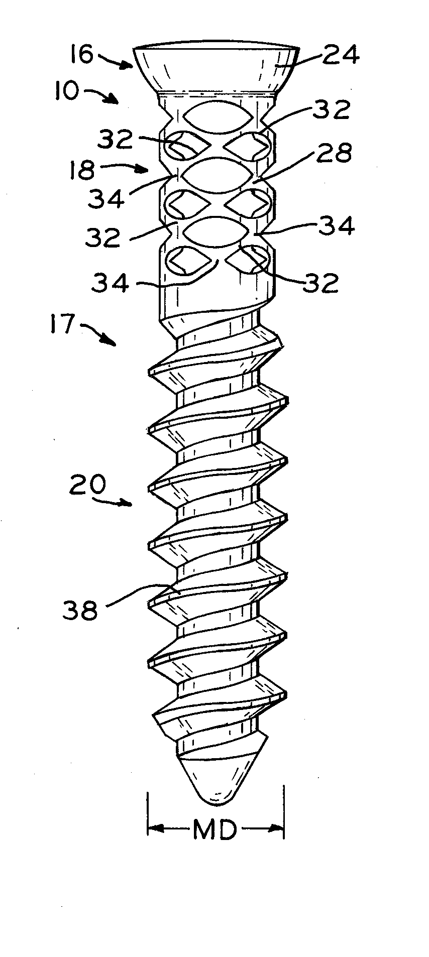
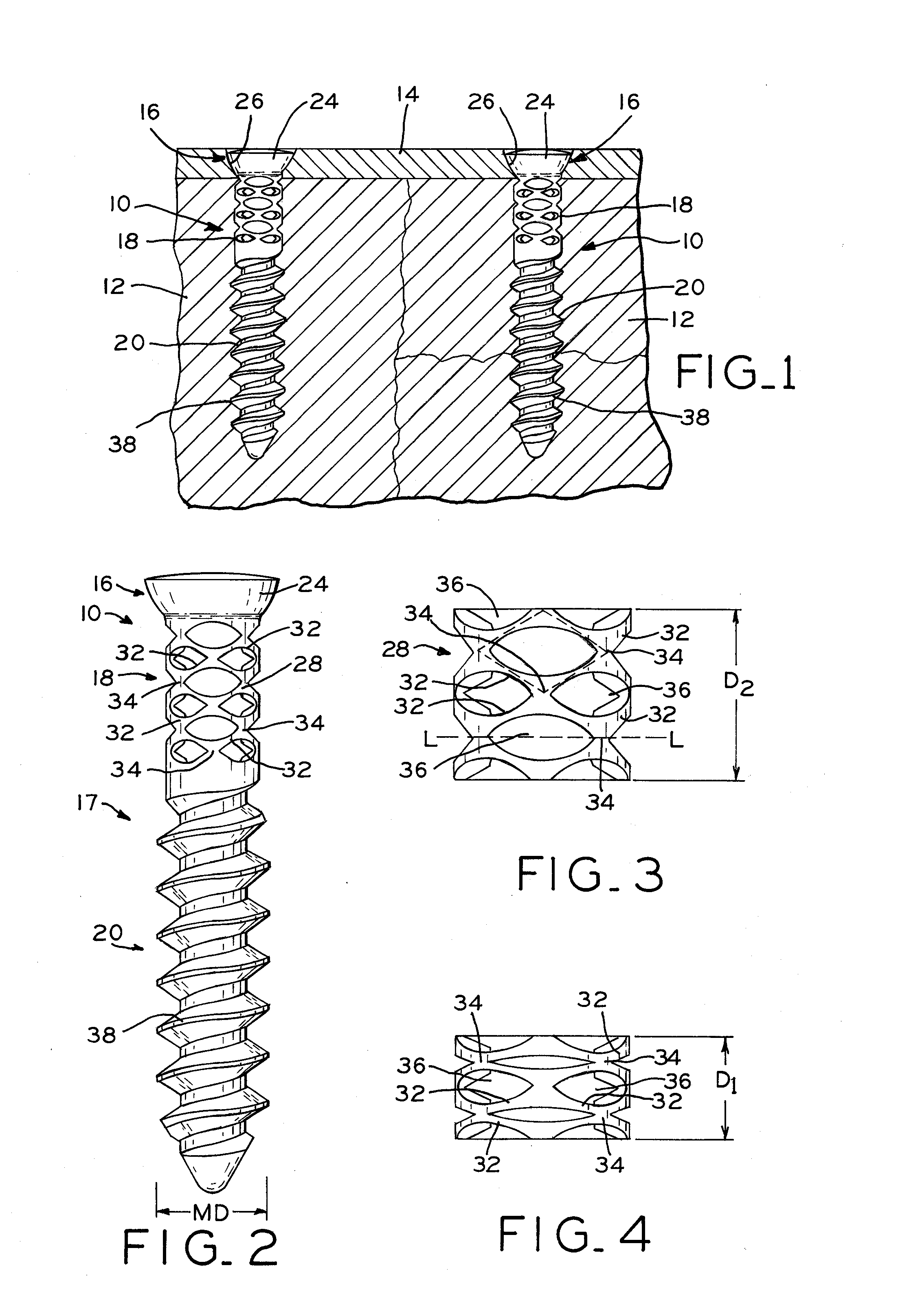
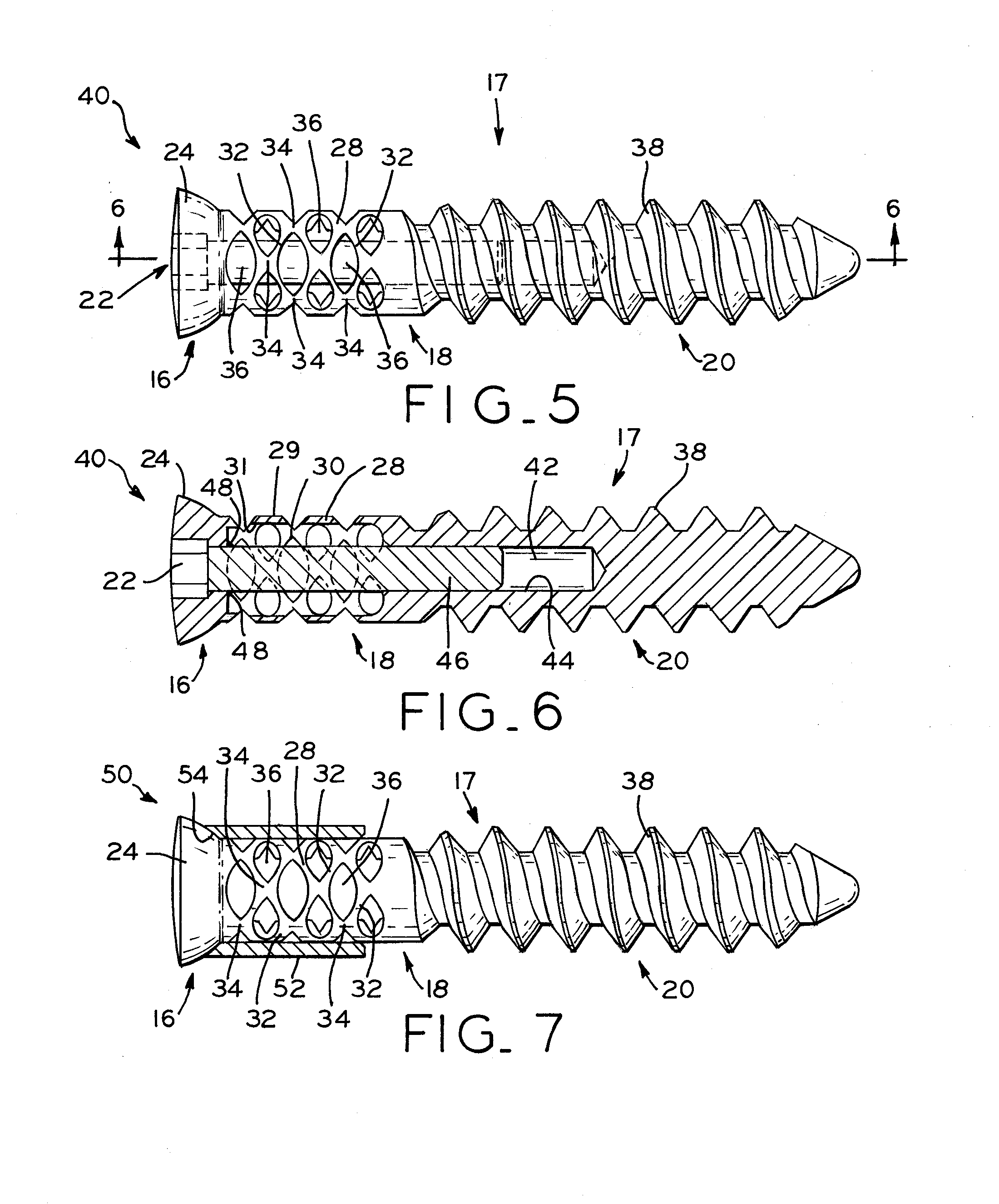
[0024]Referring to FIG. 1, bone screws 10 are shown secured within opposing portions of fractured bone 12. In this position, bone screws 10 function to retain bone plate 14 substantially adjacent bone 12, as described in detail below, and also function to retain opposing portions of fractured bone 12 adjacent one another. Referring to FIG. 2, bone screws 10 include head portion 16 and shaft 17, which includes intermediate portion 18 and threaded portion 20. Head portion 16 of bone screw 10 interacts with the surface of bone plate 14 to retain bone plate 14 against bone 12. In one exemplary embodiment, bone screw 10 is cannulated. In order to provide dynamic tension, intermediate portion 18 may be expanded during implantation of bone screws 10. Intermediate portion 18 is shown in an expanded state in FIG. 3, for example. Then, as bone 12 begins to undergo stress relaxation, the tension on bone screws 10 decreases. Specifically, bone, such as bone 12, is a viscoelastic material and, a...


PUM


Abstract

A bone screw including a head portion, an intermediate portion, and a threaded portion. The intermediate portion further includes a wave-type spring formed therein. In one exemplary embodiment, the wave-type spring is formed to have a lattice structure. In one exemplary embodiment, the wave-type spring of the intermediate portion is formed by laser cutting. By providing a wave-type spring in the intermediate portion of the bone screw of the present invention, the bone screw provides dynamic tension to maintain a bone plate or other orthopedic device in its desired position substantially adjacent a bone.

Description

BACKGROUND[0001]1. Field of the Invention[0002]The present invention relates to orthopedic devices and, particularly, to bone screws for use with orthopedic devices.[0003]2. Description of the Related Art[0004]Orthopedic devices, such as bone plates, may be used to maintain opposing portions of fractured bones substantially stationary relative to one another. For example, a bone plate may be formed as an elongate body having apertures extending therethrough and may be positioned to extend across the fracture line in a bone. Once positioned, bone screws may be inserted through the apertures to secure the bone plate to the fragments of the bone and maintain the opposing portions of the fractured bone in compression against one another.[0005]Once inserted, the tension on the bone screw is initially large enough to maintain the opposing portions of the fractured bone and / or the bone plate in compression against one another. However, the opposing portions of the fracture bone may also un...

Claims


Application Information

Patent Timeline
IPC IPC(8): A61B17/04
CPCA61B17/8625A61B17/8685A61B17/866A61B17/864
Inventor PARROTT, RUSSELL M.
Owner ZIMMER INC
Why Eureka
Try Eureka