
Cardiac stimulator with stimulation success monitoring

a technology of success monitoring and cardiac stimulators, applied in heart stimulators, electrotherapy, therapy, etc., can solve the problems of measurement uncertainty, depletion, and high energy consumption, and achieve the effect of high reliability measuremen

Active Publication Date: 2009-10-22
BIOTRONIK SE & CO KG
View PDF8 Cites 3 Cited by
  • Summary
  • Abstract
  • Description
  • Claims
  • Application Information

AI Technical Summary

Benefits of technology

[0020]Depending on the assessment, the cardiac stimulator may then control its further behavior and may trigger, for example, the delivery of an efficient stimulation pulse after inefficient stimulation and, in the absence of intrinsic conduction, increase the pulse intensity when there is inefficient stimulation and / or retain or reduce the pulse intensity when there is effective stimulation.

Problems solved by technology

A higher stimulation intensity therefore regularly also leads to a higher energy consumption.
On the other hand, there is a need to minimize the energy consumption per stimulation pulse because this energy is derived from a heart pacemaker battery, which thereby becomes depleted.
In this context, it is known that measurement of the stimulus threshold (detection of effective stimulation) is performed on the stimulation electrode, thereby resulting in measurement uncertainties due to polarization artifacts, autoshort artifacts and blanking artifacts.
Furthermore, not all types of electrodes are suitable for this method, so the known method cannot be used to an unlimited extent.

Method used


Image

  • Cardiac stimulator with stimulation success monitoring
  • Cardiac stimulator with stimulation success monitoring
  • Cardiac stimulator with stimulation success monitoring

Examples


Embodiment Construction

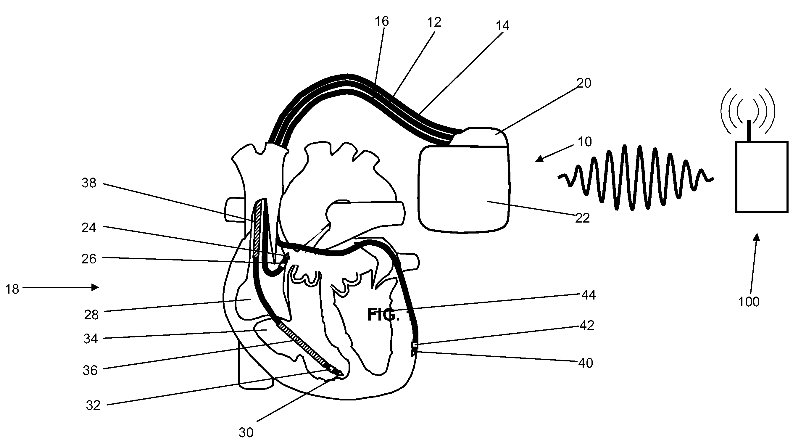
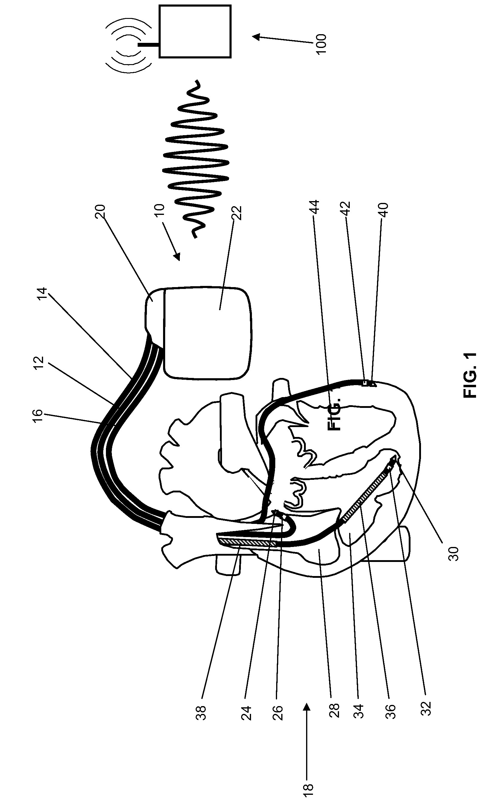
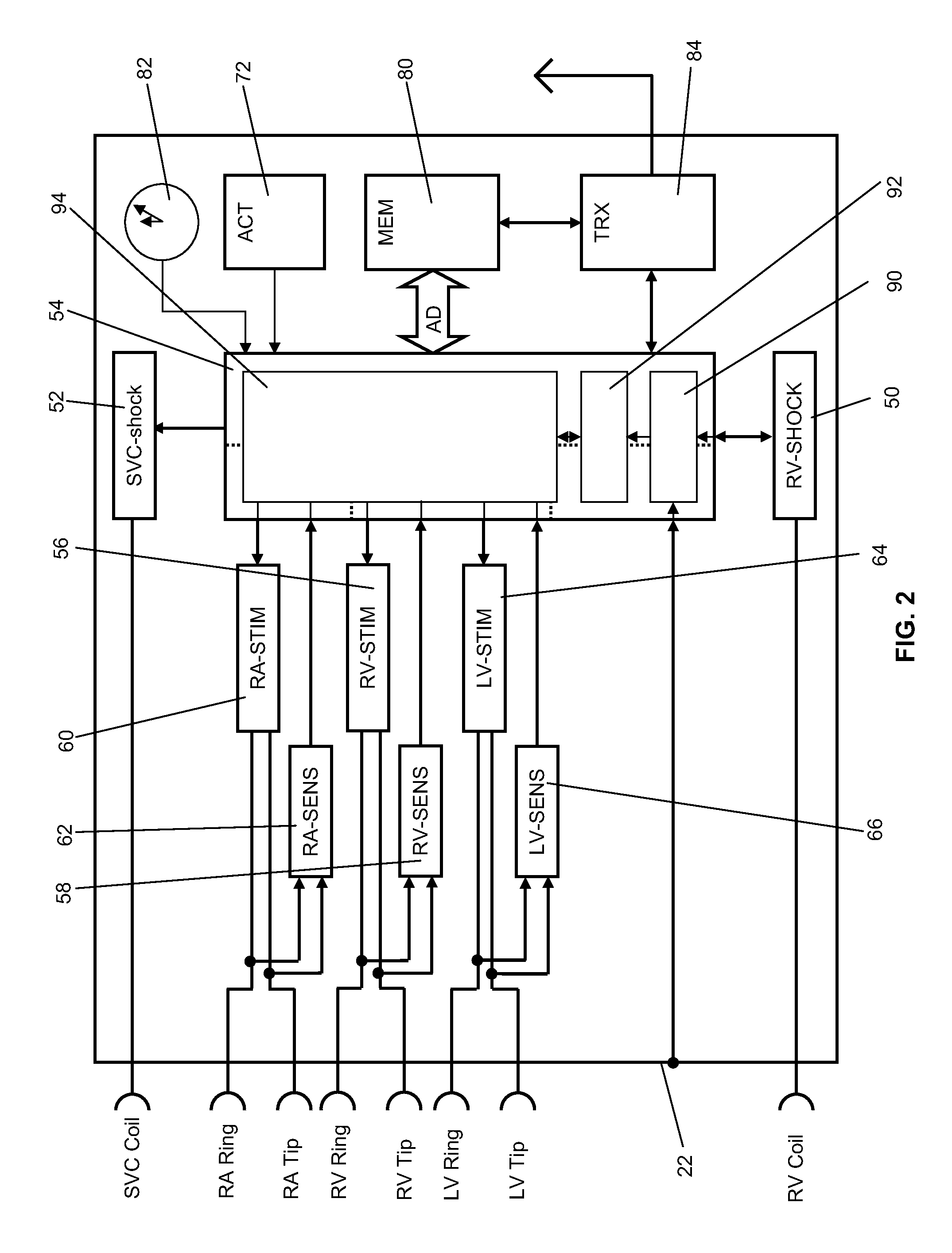
[0038]FIG. 1 shows an implantable cardiac stimulator 10 in the form of a triple-chamber heart pacemaker / cardioverter / defibrillator with electrode lines 12, 14, 16 connected to it and also connected to a heart 18. Furthermore, an external device 100 in the vicinity of the implantable cardiac stimulator 10 is also shown. The electrode lines 12, 14 and 16 are electrically connected via known standardized plug connections to contact bushings in a header (adapter housing) 20 of the cardiac stimulator 10. In this way, the electrode lines 12, 14 and 16 are also connected to electronic components in the interior of a hermetically sealed metal housing 22 of the cardiac stimulator 10. These components are presented schematically in greater detail below and determine the inventive functioning of the cardiac stimulator 10.

[0039]The electrode line 12 is a right atrial electrode line having an atrial tip electrode RA tip 24 on its distal end as well as, at a short distance therefrom, an atrial ri...


PUM


Abstract

An implantable cardiac stimulator having an at least partially electrically conductive housing, a ventricular stimulation unit connectable to left ventricular or right ventricular stimulation electrode and designed to generate ventricular stimulation pulses for stimulation of heart ventricle, having terminal for right ventricular defibrillation electrode. Has far-field electrogram detection unit (FFEDU) and stimulation success detecting unit (SSDU), of which FFEDU has first input connected to the terminal for right ventricular defibrillation electrode and second input connected to housing. FFEDU detects far-field electrocardiogram based on electric potentials applied to inputs and deliver these potentials to SSDU. SSDU has electrogram input and signal input receives a far-field electrogram generated by FFEDU and receives stimulation signal that represents a ventricular stimulation pulse generated and delivered by ventricular stimulation unit and analyzes section of received far-field electrogram immediately following delivery of ventricular stimulation impulse to determine whether it represents an effective or ineffective ventricular stimulation.

Description

BACKGROUND OF THE INVENTION[0001]1. Field of the Invention[0002]The invention relates to a cardiac stimulator with stimulation success monitoring, i.e., a cardiac stimulator such as an implantable heart pacemaker or an implantable cardioverter / defibrillator (ICD), which is independently capable of detecting the efficacy of a stimulation pulse delivered to the heart.[0003]2. Description of the Related Art[0004]Cardiac stimulators of the aforementioned type are already known in particular as implantable heart pacemakers. In the implanted and functional state, such heart pacemakers are usually connected by an electrode line of the aforementioned type to an electrode implanted in the heart and are designed to deliver electric stimulation pulses to the heart, or more specifically to individual ventricles of the heart, via the electrode. The stimulation pulses serve to energize the cardiac tissue (myocardium) of the respective ventricle and are delivered in particular when the heart does ...

Claims


Application Information

Patent Timeline
Patent Type & Authority Applications(United States)
IPC IPC(8): A61N1/39A61N1/362
CPCA61N1/3627A61N1/3962A61N1/371A61N1/3684A61N1/36842A61N1/36843A61N1/39622
Inventor DOERR, THOMASTSCHERCH, FRANKTIETZE, ULRICH
Owner BIOTRONIK SE & CO KG
Learn More