Spinal implant apparatus and methods

a technology of spinal implants and implants, applied in the field of spinal implants, can solve the problems of abnormal movement, less than desirable coronal and/or sagittal alignment of the spine, thinning of the disc, etc., and achieve the effects of improving success rate, speeding recovery, and reducing patient risk

Active Publication Date: 2009-10-22
STRYKER EURO OPERATIONS HLDG LLC
View PDF99 Cites 57 Cited by
  • Summary
  • Abstract
  • Description
  • Claims
  • Application Information

AI Technical Summary

Benefits of technology

[0014]The present invention is constructed to decrease patient risk, speed recovery, and substantially improve success rates in terms of restoration of normal spinal confirmation and neurological decompression. This is achieved by providing the surgeon with a spacer that is much more readily movable into an ...

Problems solved by technology

These problems include, for example, degeneration, bulging, herniation, thinning of a disc, or abnormal movement, and the pain that is experienced generally is attributable to friction or pressure that inevitably occurs when one adjacent vertebra exerts uneven pressure, or when both adjacent vertebrae exert such pressure, on the disc.
Existing IF techniques fail to enable fine positioning of an implant device with respect to the vertebrae.
The result may be less than desirable coronal and/or sagittal alignment of the spine.
Existing IF procedures are further limited in other ways.
In existing IF techniques, this requires extensive cutting and...

Method used


Image

  • Spinal implant apparatus and methods
  • Spinal implant apparatus and methods
  • Spinal implant apparatus and methods

Examples


Embodiment Construction

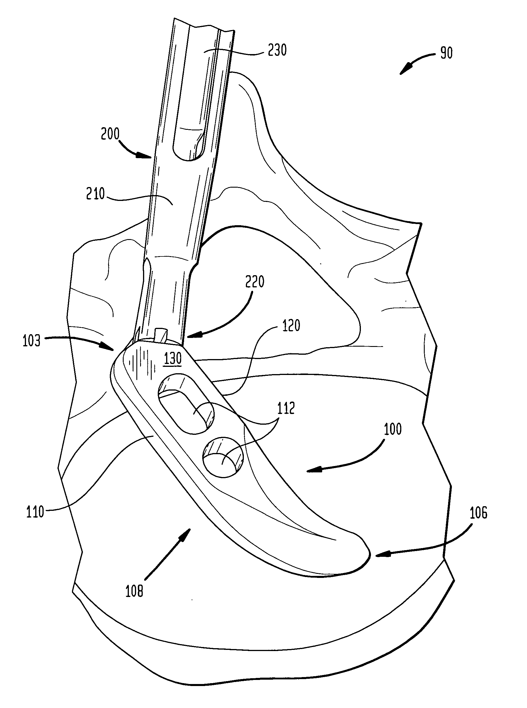
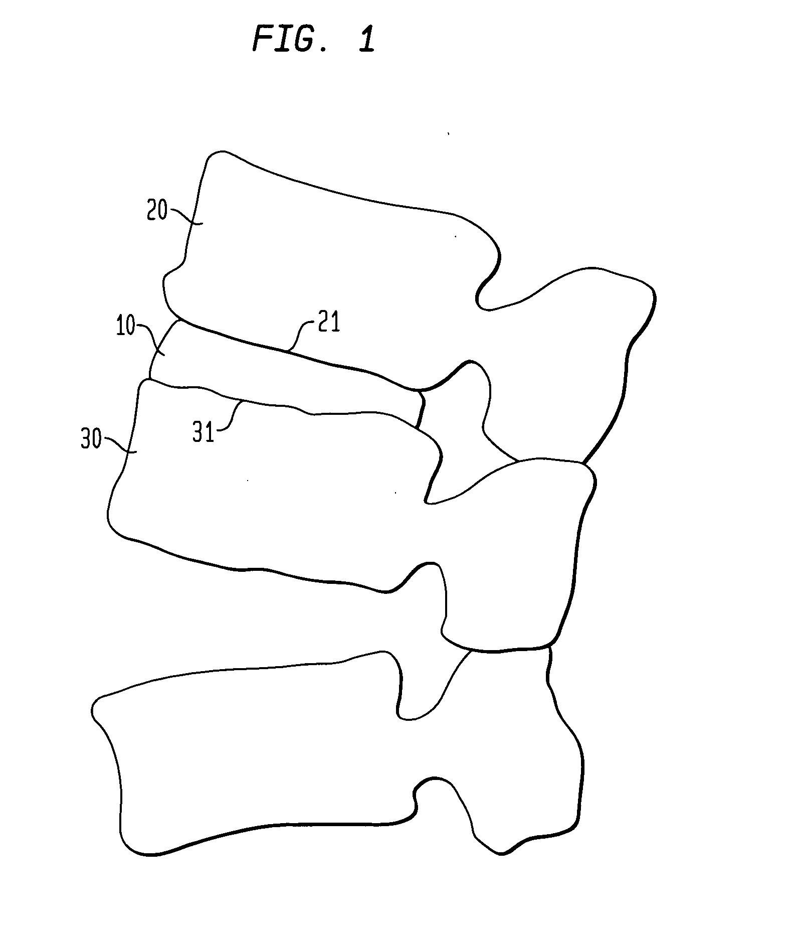
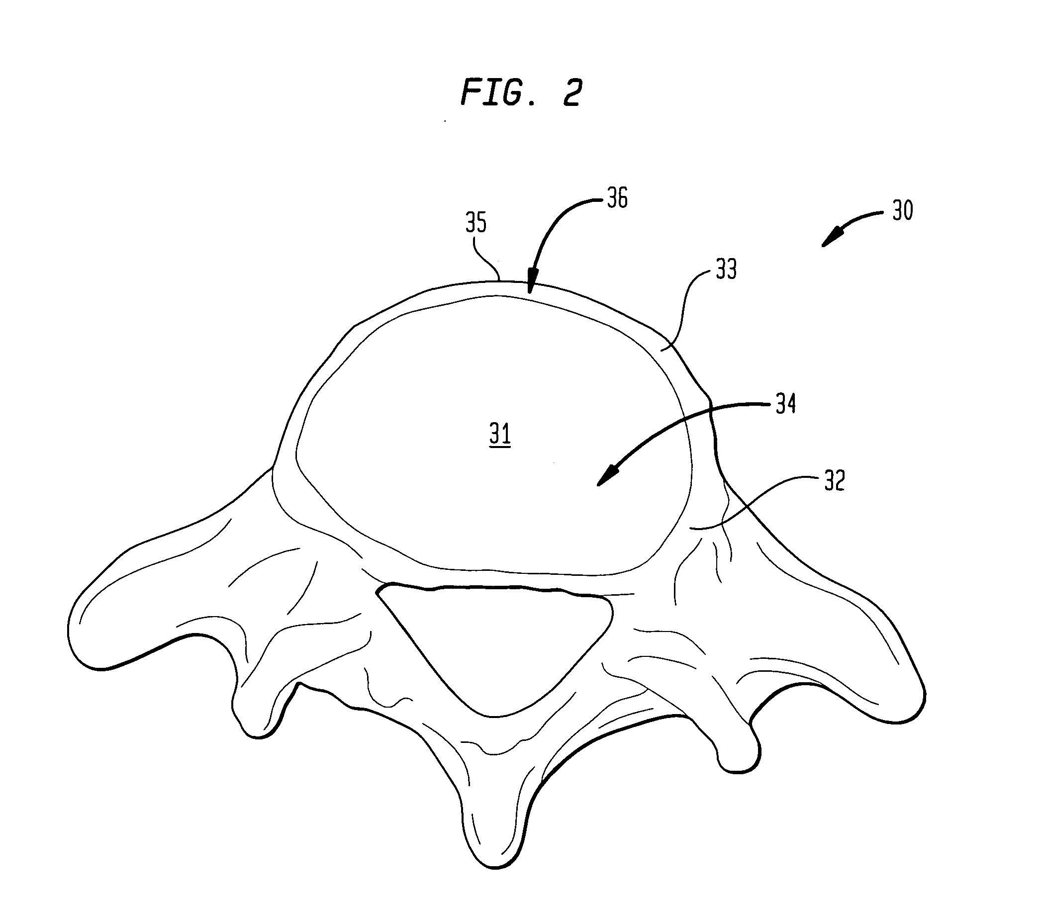
[0055]Referring to FIG. 4, a spinal implant apparatus 90 of the present invention includes a prosthetic intervertebral spacer 100 and a positioning tool 200 for fine and minimally invasive manipulation of spacer 100 within a patient in need of lumbar interbody fusion (“LIF”) surgery. Apparatus 90 allows spacer 100 to be easily and consistently positioned to a desirable location 36 as represented in FIG. 5, where desirable location 36 is near the anterior region 35 of inferior vertebra 30 (a similar desirable location located near the anterior region of superior vertebra 20). Therefore, spacer 100 is shown in FIG. 5 as being positioned substantially between the upper surface of cortical rim 33 of inferior vertebra 30 and the lower surface of the cortical rim of superior vertebra 20. Positioned in desirable location 36, spacer 100 is maximally supported by cortical rim 33 (and a like cortical rim of superior vertebra 20), and spacer 100 better promotes alignment and lordosis than it w...


PUM


Abstract

A method of inserting and positioning an intervertebral spacer is provided. The spacer includes a longitudinal axis, an on-axis interface coincident with or parallel to the longitudinal axis, and an off-axis interface angled to the longitudinal axis. The spacer's front end may be curved. The method may include inserting the spacer into the disc space utilizing a tool to engage an on-axis interface and then to engage one or more of the off-axis interfaces, which may be used for further modification of the spacer. The tool is moved substantially along a single insertion direction, which may be substantially parallel to a posterior-anterior axis of the disc space. The method may result in the longitudinal axis of the spacer being perpendicular to the insertion direction, or substantially parallel to a medial-lateral axis of the disc space. The spacer may also be positioned in an anterior aspect of the disc space.

Description

CROSS-REFERENCE TO RELATED APPLICATIONS[0001]This application claims the benefit of the filing dates of U.S. Provisional Patent Application No. 61 / 040,821 filed Mar. 31, 2008, and entitled SPINAL IMPLANT APPARATUS AND METHOD OF USING THE SAME, and U.S. Provisional Patent Application No. 61 / 091,505 filed Aug. 25, 2008, and entitled SPINAL IMPLANT APPARATUS, the disclosures of which are hereby incorporated herein by reference.BACKGROUND OF THE INVENTION[0002]The present invention relates to a spinal implant apparatus and a method of using that apparatus to treat a spine disorder. More particularly, the present invention relates to an implant apparatus, which includes a steerable spacer and a manipulation device or positioning tool, and a method for using the positioning tool to position the spacer at a desirable position at the anterior region of a vertebra. Further, the present invention relates to an intervertebral spacer arranged for selectable steerage to a location of interest be...

Claims


Application Information

Patent Timeline
IPC IPC(8): A61F2/44
CPCA61F2/4455A61F2/447A61F2002/30133A61F2002/30281A61F2002/30507A61F2002/30518A61F2002/30538A61F2002/3054A61F2002/30579A61F2002/30604A61F2002/30617A61F2002/4628A61F2002/4629A61F2220/0025A61F2230/0015A61F2230/0086A61F2250/0006A61F2250/0097A61F2310/00023A61F2/4611A61F2002/30537A61F2002/4615
Inventor THIBODEAU, LEE L.
Owner STRYKER EURO OPERATIONS HLDG LLC
Why Eureka
Try Eureka