Differentiating Between Abnormal Sample Viscosities and Pipette Clogging During Aspiration

a technology of abnormal sample viscosity and pipette, which is applied in the direction of fluid-tightness measurement, instruments, machines/engines, etc., can solve the problem of failure of the aspiration process and achieve the effect of lowering the viscosity

Active Publication Date: 2009-10-29
SIEMENS HEALTHCARE DIAGNOSTICS INC
View PDF23 Cites 25 Cited by
  • Summary
  • Abstract
  • Description
  • Claims
  • Application Information

AI Technical Summary

Benefits of technology

[0012]It is therefore an object of this invention to provide a method for differentiating between a clogged liquid sample and a sample having an abnormally elevated viscosity during a liquid aspiration process. This is accomplished by first confirming from analysis of the aspiration pressure (vacuum) profile that a minimum sample volume exists. Next, the standard deviation of the residuals is measured from a linear regression analysis of the aspiration pressure profile over a shortened final portion of the aspiration pressure profile. If the standard deviation of the residuals is greater than a predetermined critical value, then the

Problems solved by technology

If the standard deviation of the residuals is greater than a predetermined critical value, then the aspiration process may have failed due to a leak,

Method used


Image

  • Differentiating Between Abnormal Sample Viscosities and Pipette Clogging During Aspiration
  • Differentiating Between Abnormal Sample Viscosities and Pipette Clogging During Aspiration
  • Differentiating Between Abnormal Sample Viscosities and Pipette Clogging During Aspiration

Examples


Embodiment Construction

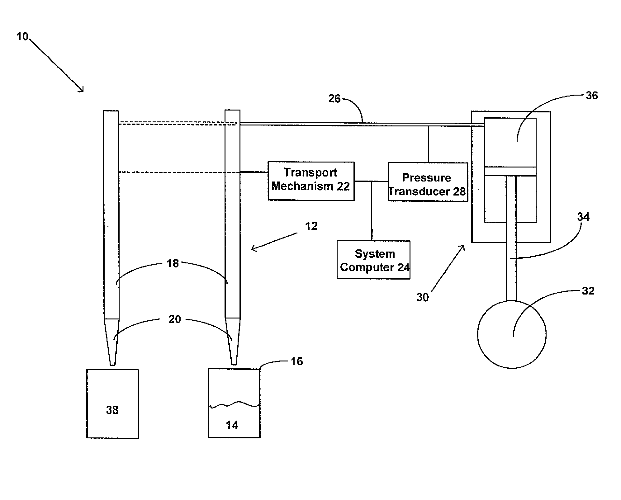
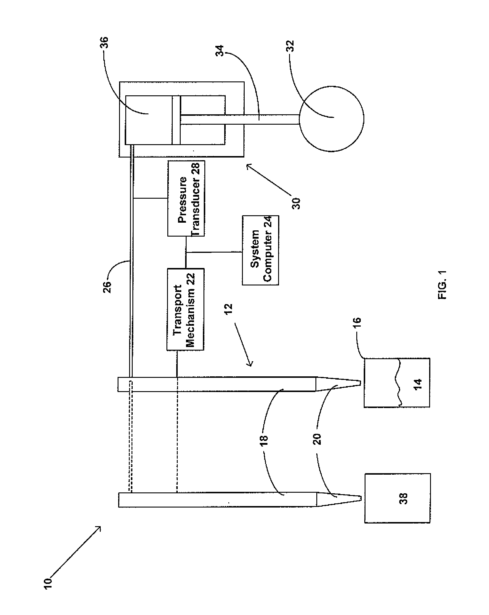
[0021]FIG. 1 illustrates a liquid aspirating and dispensing system 10 useful in practicing the present invention which includes a pipette 12 for aspirating and dispensing liquid such as a sample liquid 14 contained in a container 16, like described in co-pending U.S. patent application Ser. No. 11 / 857,922 assigned to the assignee of the present application and incorporated herein by reference. Although one such sample liquid 14 is shown for the purpose of describing the liquid dispensing system 10, it will be apparent to those skilled in the art that any number of sample liquid containers 16 can be present in an automated clinical analyzer like described in co-pending U.S. patent application Ser. No. 11 / 941,204 assigned to the assignee of the present application and incorporated herein by reference, including patents and patent applications incorporated therein by reference and like described in co-pending U.S. patent application Ser. No. 10 / 862,507 assigned to the assignee of the p...


PUM


Abstract

A method for differentiating between a liquid sample having clogs therein and a liquid sample having an abnormally elevated viscosity during a liquid aspiration process by relating the ratio between the maximum negative pressure during aspiration and an equilibrium pressure prior to dispensation to viscosity.

Description

FIELD OF THE INVENTION[0001]The present invention relates to the aspiration of an amount of liquid from a container, and more particularly, to an improved method for differentiating between a clogged liquid sample and a sample having an abnormally elevated viscosity during a liquid aspiration process.BACKGROUND OF THE INVENTION[0002]Fully automated diagnostic analyzers are commercially available to perform chemical assays and immunoassays of biological liquids such as urine, blood serum, plasma, cerebrospinal liquids and the like. Generally, reactions between an analyte in a patient sample and reagents used during the assay generate a signal from which the concentration of analyte in the patient sample may be calculated. Such automated analyzers generally use an aspirating means such as a sampling tip, or probe or needle, to transfer desired volumes of liquid samples or liquid reagents between receptacles, such as between sample containers, reagent containers and reaction cuvettes d...

Claims


Application Information

Patent Timeline
IPC IPC(8): G01N11/08
CPCG01N2035/1018G01N35/1016
Inventor KAPLIT, MICHAEL
Owner SIEMENS HEALTHCARE DIAGNOSTICS INC
Why Eureka
Try Eureka