Method for Reducing Fouling of Coker Furnaces

a furnace and coker technology, applied in the direction of hydrocarbon oil treatment, corrosion/fouling inhibition of treatment apparatus, cracking process, etc., can solve the problems of furnace decoking, high operating cost, operation must be shut down, etc., to reduce furnace fouling, reduce furnace fouling, and increase the aromaticity of the bottom stream

Active Publication Date: 2009-10-29
BECHTEL ENERGY TECH & SOLUTIONS INC
View PDF10 Cites 13 Cited by
  • Summary
  • Abstract
  • Description
  • Claims
  • Application Information

AI Technical Summary

Benefits of technology

[0008]In one embodiment, the invention provides a method for reducing furnace fouling in a delayed coking process in which the coker feed is supplied to the bottom of the coker fractionator to produce an overhead stream, a bottoms stream and at least one intermediate stream and the aromaticity of the bottoms stream is increased by combining with the bottoms stream at least one added stream upstream of the coker furnace to produce a modified stream.
[0009]In another embodiment, the invention provides a method for reducing furnace fouling in a delayed coking process in which the coker feed is supplied to the coker furnace without first passing the feed through the fractionator and the aromaticity of the feed is increased by combining with the feed at least one added stream upstream of the coker furnace to produce a modified stream.

Problems solved by technology
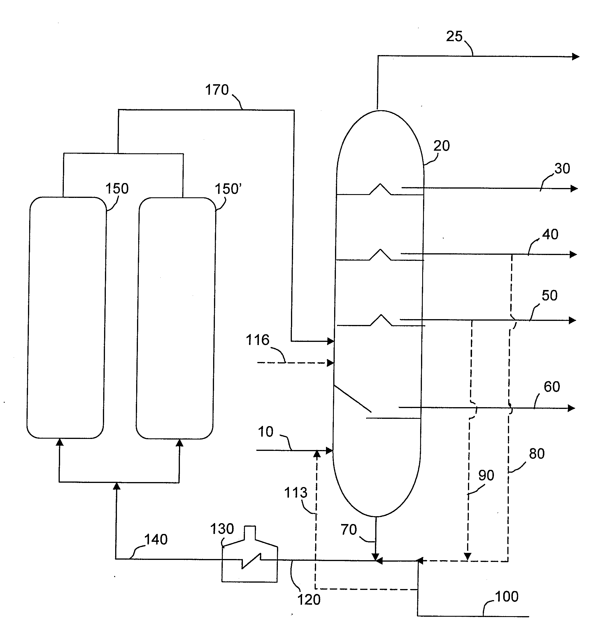
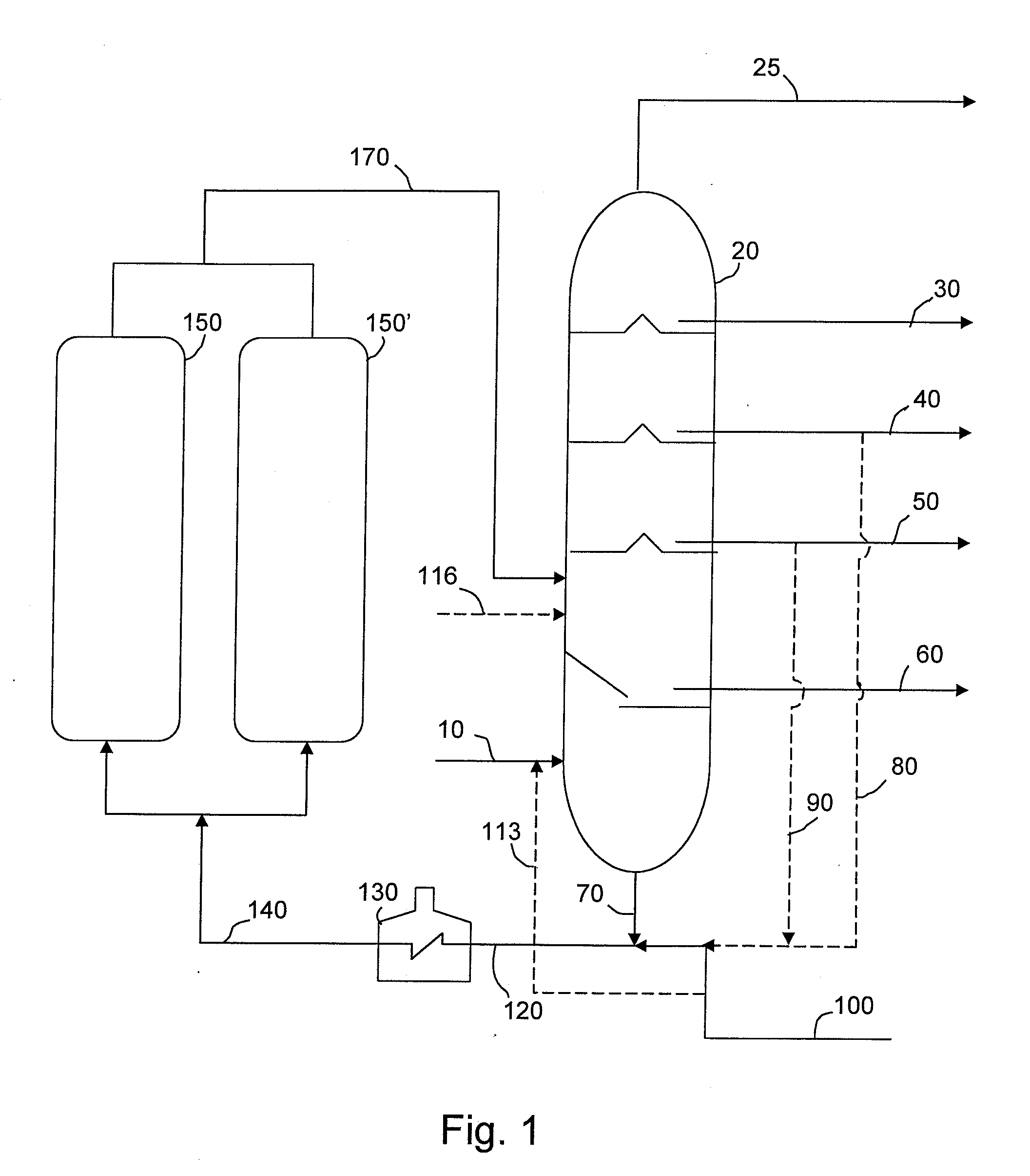
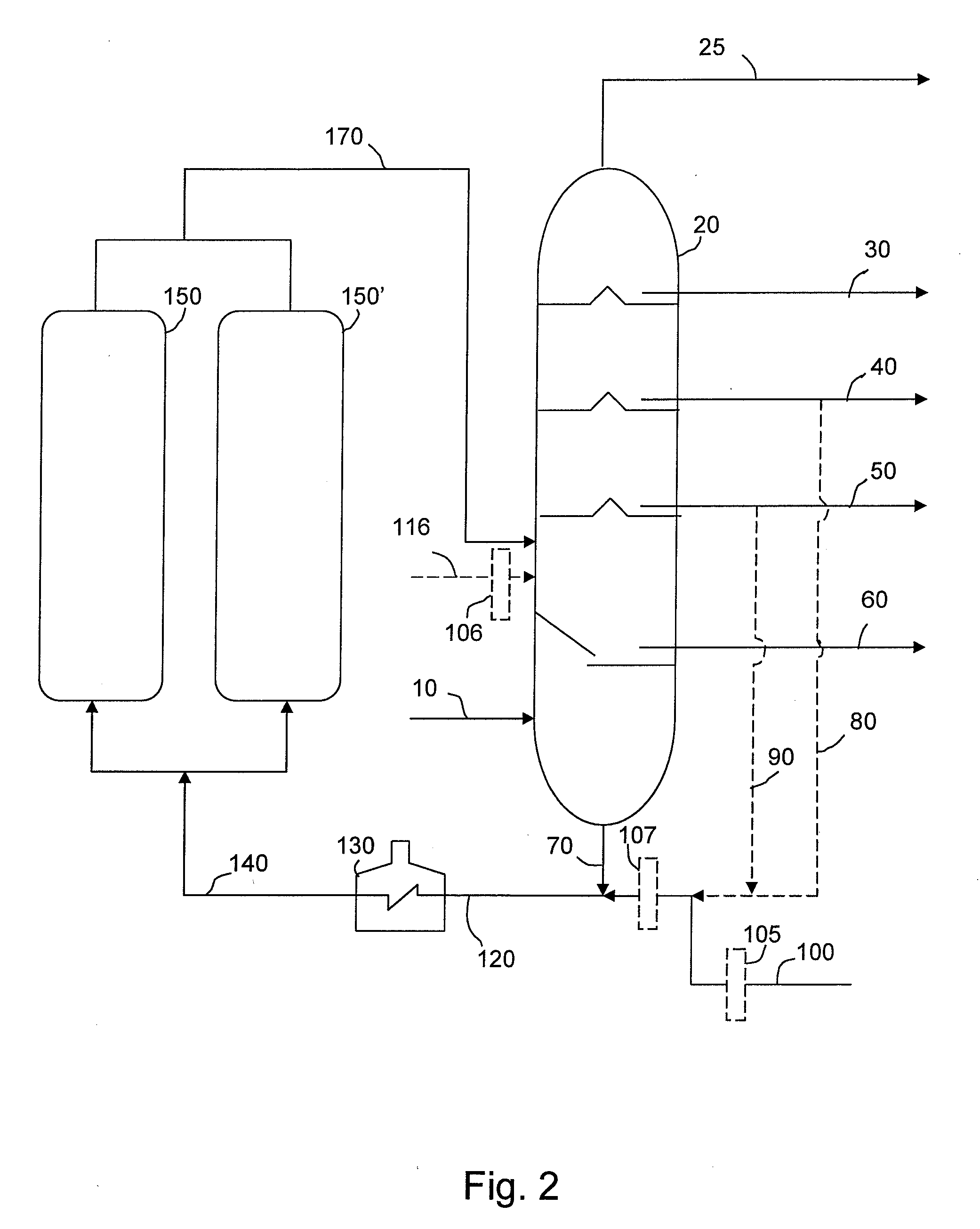
When coke deposits reach excessive levels, the operation must be shut down and the furnace de-coked.
Frequent interruptions for cleaning can lead to high operating costs due to increased amounts of time the operation is off-line, in addition to the costs of the de-coking operations.
Although the process is referred to as “coking”, coke is often the least valuable product of the operation.
This approach reduces furnace fouling when using conventional coker feedstocks, but is not adequate to control furnace fouling when using coker feedstocks having a high propensity for furnace fouling.
Although small amounts of feedstocks having a high propensity for furnace fouling can be blended in with conventional coker feedstocks, using them as the primary source of feed or blending them in large amounts with conventional feeds to a coker has not heretofore been feasible because of furnace fouling problems.
Thus, fouling of coker furnaces remains a costly problem.

Method used


Image

  • Method for Reducing Fouling of Coker Furnaces
  • Method for Reducing Fouling of Coker Furnaces
  • Method for Reducing Fouling of Coker Furnaces

Examples


example 1

[0068]Coking Propensities of Feedstocks Modified with Various Gas Oils

[0069]A resid feedstock having physical properties as shown in Table I was tested using the coking propensity apparatus described in International Publication No. WO 01 / 53813. Also tested were blends consisting of about 80 wt % of the resid with about 20 wt % of each of the gas oils listed below in Table I.

TABLE IGas Oil PropertiesGASOIL #DESCRIPTION1Aromatic needle coker gas oil2Gas oil 1, hydrotreated with a Co / Mo catalyst to givea hydrogen uptake of about 400 SCFB3Gas oil 1, hydrotreated with a Ni / Mo catalyst togive a hydrogen uptake of about 1,000 SCFB4Less aromatic needle coker gas oil, hydrotreated witha Co / Mo catalyst to give a hydrogen uptake of about 370 SCFB5Blend of virgin non-needle coker gas oil and lessaromatic needle coker gas oil, hydrotreated with a Ni / Mocatalyst to give a hydrogen uptake of about 480 SCFB6Flash zone gas oil from a delayed coking operationfor production of fuel coke

[0070]The prope...

example 2

[0073]Coking Propensities of Feedstocks Modified with Fractionated Gas Oils

[0074]Gas oils 1 and 3 were each fractionated to produce a 750-850° F. fraction and an 850+° F. fraction. These fractions were mixed with the resid from Example 1 in a proportion of about 80 wt % resid and about 20 wt % gas oil. The properties and OCFT data for these samples are summarized in Table IV.

TABLE IVCoking Propensity Results (Example 2)RunAvg. LiquidOCFTCorrectedNo.Gas Oil ModifierTemp (° F.)(min)OCFT (min)202None700385236203None756 85204208None735157226AVG:22220416 wt % of 750-850° F.753138309fraction of gas oil #120520 wt % of 850+° F.734187263fraction of gas oil #120620 wt % of 750-850° F.747189365fraction of gas oil #320718.3 wt % of 850+° F.705231160fraction of gas oil #3

[0075]The data in Table IV demonstrate that the 750-850° F. fraction is more effective than the 850+° F. fraction at slowing coke formation, particularly in the case of hydrotreated gas oil #3.

example 3

[0076]Coking Propensities of Feedstocks Modified with Fractionated Gas Oils

[0077]Gas oil 6, which was less effective at slowing coke formation than the other gas oils tested in Example 1, was fractionated to produce a 750-850° F. fraction and a fraction boiling below 950° F. These fractions were mixed with the resid from Example 1 in a proportion of about 80 wt % resid and about 20 wt % gas oil. The properties and OCFT data for these samples are summarized in Table V.

TABLE VCoking Propensity Results (Example 3)RunAvg. LiquidOCFTCorrectedNo.Gas Oil AdditiveTemp (° F.)(min)OCFT (min)213None731162212219None724200243AVG:22721720 wt % of 750-850° F.742139238fraction of gas oil #621820 wt % of 950−° F.737165250fraction of gas oil #6216Gas oil #6731173226

[0078]Table V illustrates results similar to those of Example 2, specifically, that separating out the highest molecular weight fraction of the gas oil makes the gas oil more effective at slowing the onset of coke formation.


PUM

PropertyMeasurementUnit
boiling pointaaaaaaaaaa
operating temperatureaaaaaaaaaa

Abstract

A method for reducing furnace fouling in a delayed coking process comprising (a) supplying at least one feed to a delayed coking unit comprised of coker furnace, at least two coke drums and a coker fractionator, (b) increasing the aromaticity of the feed to produce a modified stream by combining with the feed upstream of the coker furnace at least one added stream selected from the group consisting of an aromatic gas oil, a hydrotreated aromatic gas oil and combinations thereof, (c) introducing the modified feed stream into the coker furnace, d) heating the modified feed stream to a coking temperature in the coker furnace to produce a heated modified stream, and e) transferring the heated modified stream from the coker furnace to a coke drum.

Description

BACKGROUND OF THE INVENTION[0001]This invention relates to methods for reducing furnace fouling in delayed coking processes, and more particularly in delayed coking processes in which the coker feedstock has a high propensity for furnace fouling.[0002]Delayed coking is a non-catalytic thermal cracking process for treating various low value residual (“resid”) streams from petroleum refinery processes. The treatment enhances the value of such streams by converting them to lower boiling cracked products. In a conventional delayed coking process, as described for example in U.S. Pat. No. 4,455,219, feedstock is introduced to a fractionator to produce an overhead stream, a bottoms stream and at least one intermediate stream. The fractionator bottoms stream including recycle material is heated to coking temperature in a coker furnace. The heated feed is then transferred to a coke drum maintained at coking conditions of temperature and pressure where the feed decomposes to form coke and vo...

Claims


Application Information

Patent Timeline
Patent Type & Authority Applications(United States)
IPC IPC(8): C10G9/14
CPCC10B57/045C10G75/04C10G9/16
Inventor NEWMAN, BRUCE A.ALEXANDER, KEITH D.HUGHES, GARY C.ROTH, JAMES R.
Owner BECHTEL ENERGY TECH & SOLUTIONS INC
Why Eureka
Try Eureka