Device for damping the armature stroke in solenoid valves

a solenoid valve and armature stroke technology, which is applied in the direction of valve housings, valve operating means/releasing devices, mechanical devices, etc., can solve the disadvantages of the aperture function of the hydraulic cross section and the relatively high manufacturing cost, and achieve the effect of small aperture diameter, good aperture function and very cost-effective manufacturing

Inactive Publication Date: 2009-10-29
ROBERT BOSCH GMBH
View PDF13 Cites 8 Cited by
  • Summary
  • Abstract
  • Description
  • Claims
  • Application Information

AI Technical Summary

Benefits of technology

[0011]The cup-shaped damping element according to the present invention may be manufactured very cost-effectively via punching or bending processes or also, when made of plastic, by way of injection molding. The damping element according to the present invention may be fastened directly on the armature or on a shaft cooperating with the armature via pressing-on, pressing-in, welding-on, or caulking.
[0012]The proposed damping element is characterized by a good aperture function in addition to its multiple functionality since there is a small length/diameter ratio with respect to the aperture cross sections introduced into the base and by the fact that small aperture diameters may easily be implemented. The aperture cross sections may also be implemented in the lateral surface of the cup-shaped or hat-shaped damping element. The aperture cross sections may be bore holes or slots through which the fluid, e.g., oil, contained in an interior space of a solenoid valve overflows, thereby generating the damping effect. The

Problems solved by technology

Bore holes, which represent hydraulic cross sections, are applied eccentrically and therefore generate relatively high manufacturing costs.
Since these bore holes are also applied to rela

Method used


Image

  • Device for damping the armature stroke in solenoid valves
  • Device for damping the armature stroke in solenoid valves
  • Device for damping the armature stroke in solenoid valves

Examples


Embodiment Construction

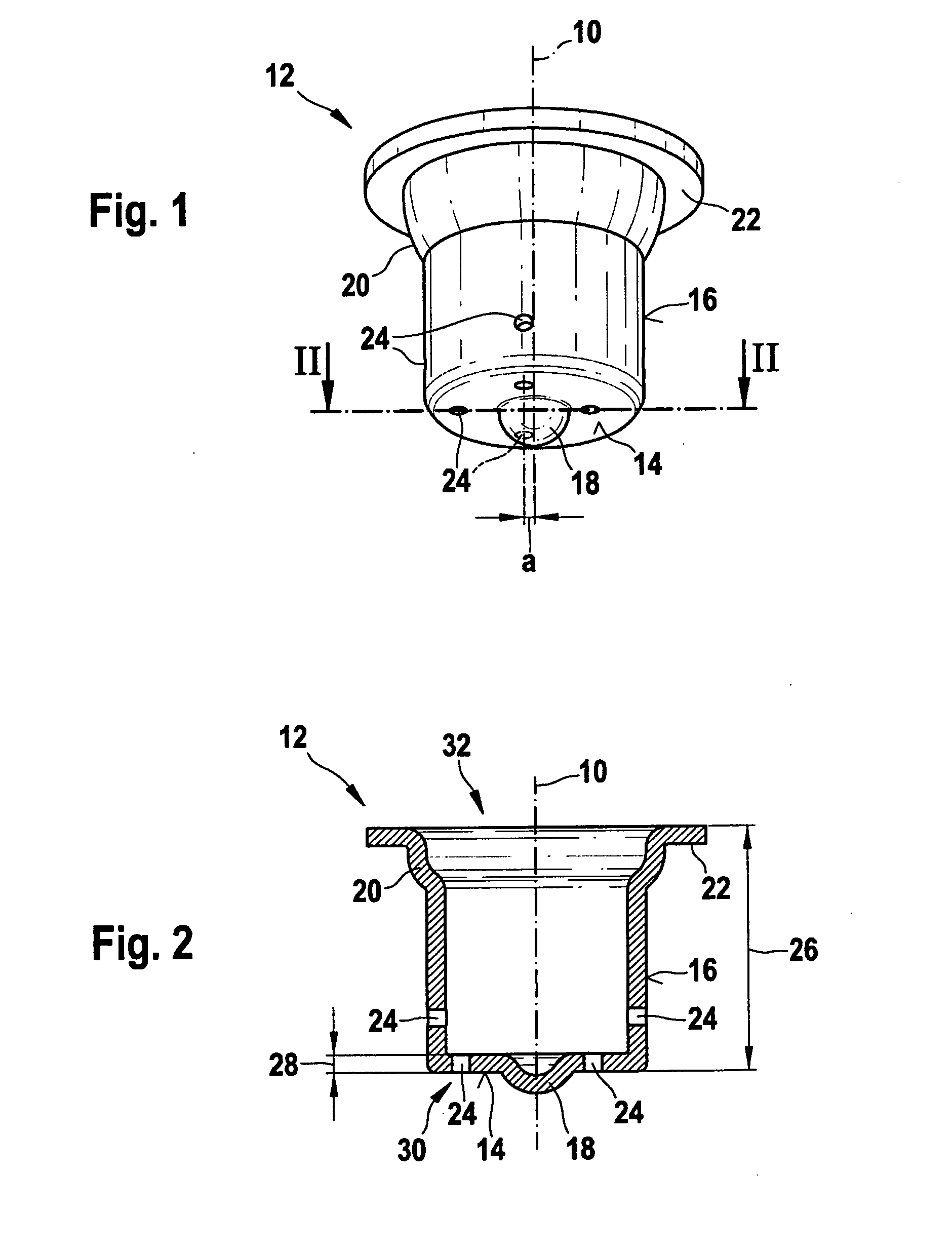
[0020]The damping element according to the present invention is shown in a perspective view in FIG. 1.

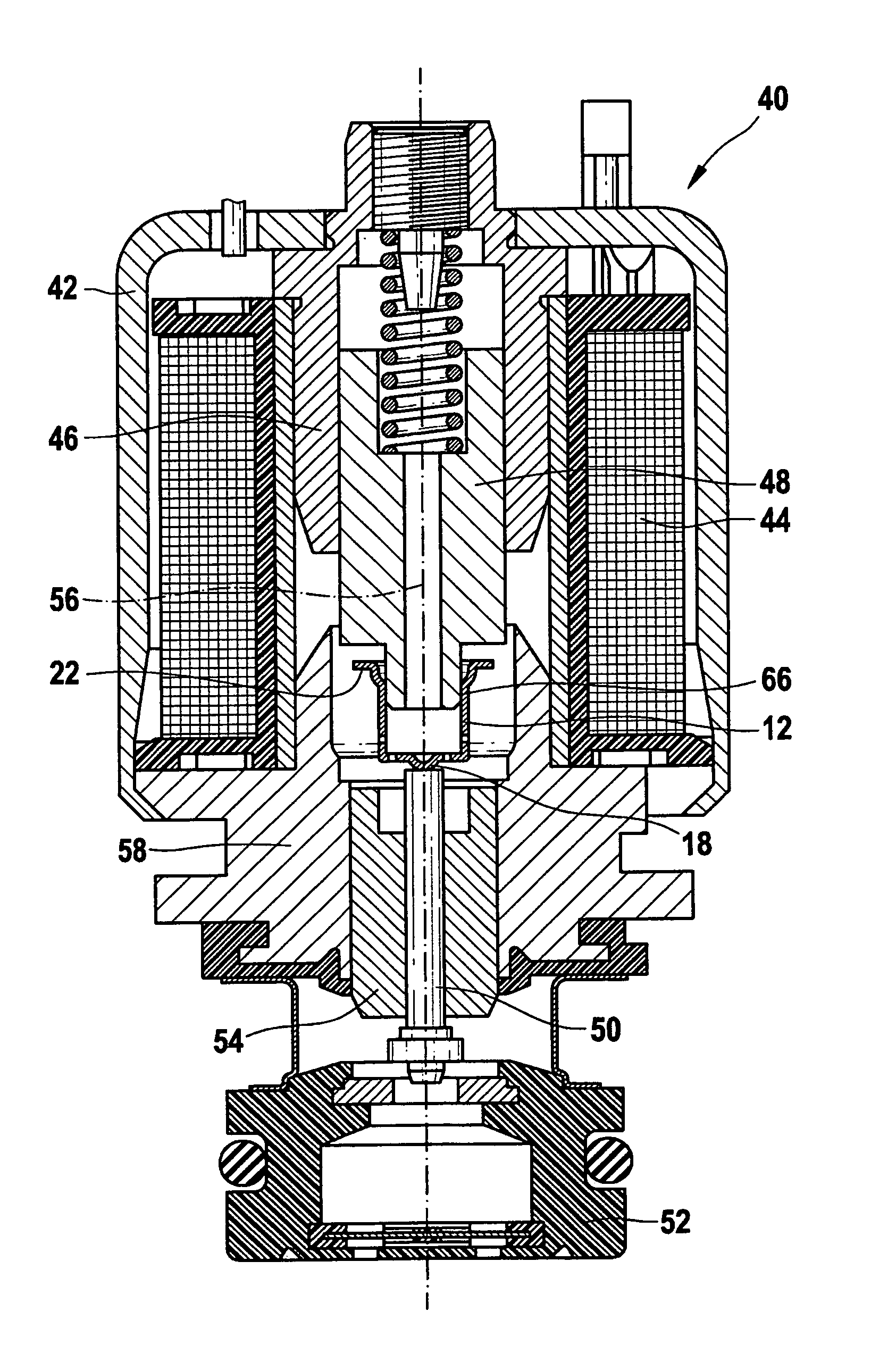
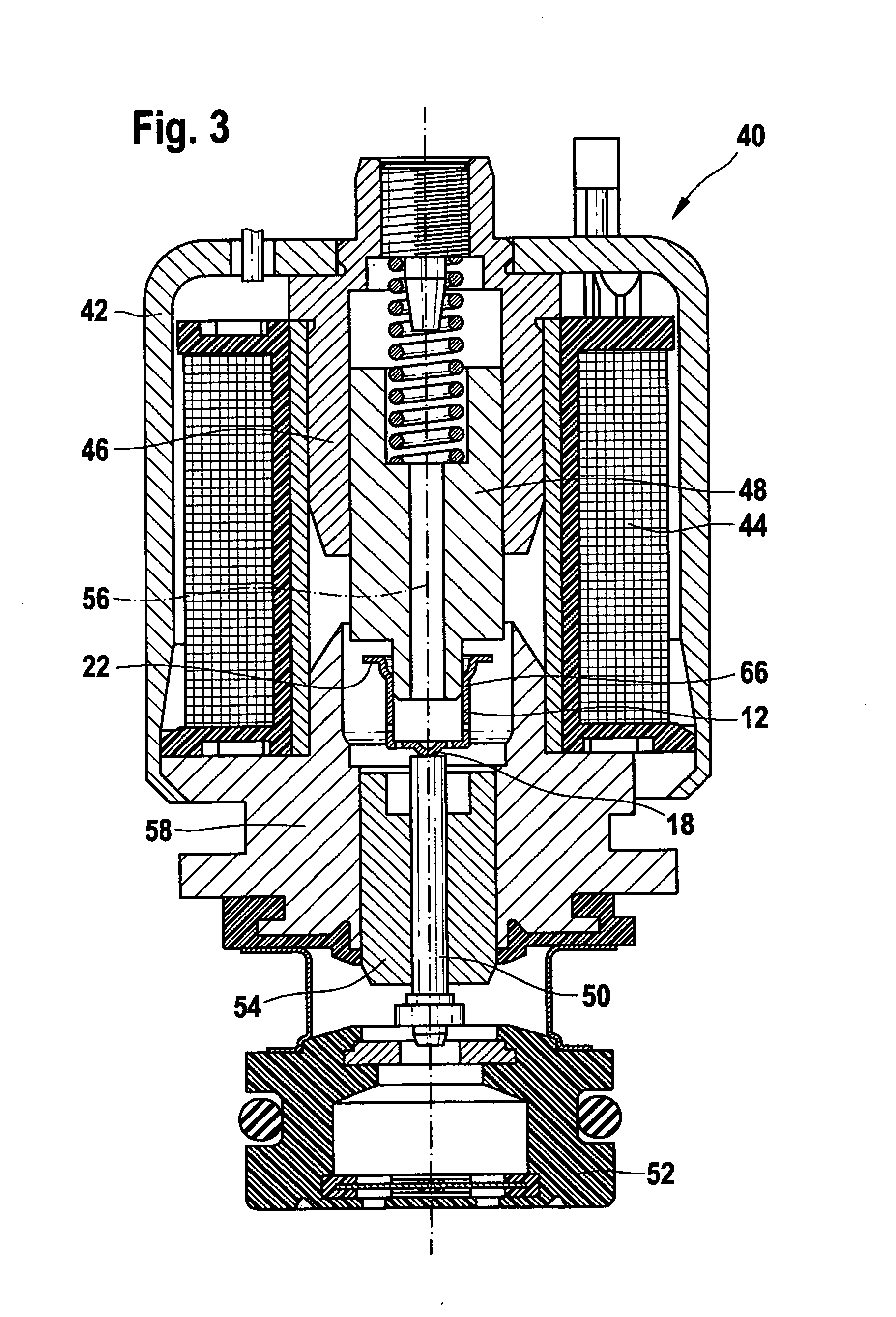
[0021]Damping element 12 has a generally cup-shaped geometry (see FIG. 2) and is built symmetrically with respect to a symmetry axis 10. Damping element 12 includes a base surface 14 and a lateral surface 16. Multiple aperture cross sections 24, which may be produced as bore holes, are provided in base surface 14 of damping element 12. Alternatively, aperture cross sections 24 for an overflowing fluid, such as oil for example, generating the damping may also be provided in lateral surface 16 or in base surface 14 and lateral surface 16 of damping element 12. Aperture cross sections 24 may have a circular, oval, slot-shaped, rectangular, square, or even kidney-shaped design or be designed in any other geometry. Furthermore, a coupler point 18, which is designed as a head-shaped elevation in the exemplary embodiment of damping element 12 shown in FIG. 1, is situated in base surface 14...


PUM


Abstract

A solenoid valve for actuating an actuator having an armature and an electromagnet. The stroke of the armature is transferred to the actuator via a transfer element. The armature is accommodated in a guide of a housing of the solenoid valve. A damping element is situated between the armature and the transfer element, at least one aperture cross section being formed perpendicularly or coaxially to a symmetry axis in the damping element.

Description

FIELD OF THE INVENTION[0001]The present invention relates to a device for damping the armature stroke in solenoid valves which are used as actuators in the automotive industry, for example.BACKGROUND INFORMATION[0002]German Patent Application No. DE 196 50 865 A1 describes a solenoid valve. This solenoid valve is used for controlling an injector of a fuel injection device having a valve needle whose opening and closing is controlled by a solenoid valve. This solenoid valve has an electromagnet, an armature, and a valve member which is moved by the armature and acted upon in the closing direction by a valve spring. The valve member cooperates with a valve seat, the armature having a two-piece design with a first armature part which, relative to a second armature part, is displaceable under the effect of its inert mass in the closing direction of the valve member against the force of a restoring spring. A part of a hydraulic damping device is provided on the first armature part which ...

Claims


Application Information

Patent Timeline
IPC IPC(8): F16K31/06
CPCF16K31/0689F16K31/0655F16K27/029H01F7/16
Inventor HOFMANN, TILOFLEIG, CLAUS
Owner ROBERT BOSCH GMBH
Why Eureka
Try Eureka